

Question: Design Problem: A circuit given in Figure has four inputs (say Xo, X1, X2 and X3) and two outputs (say Y and Z). X2
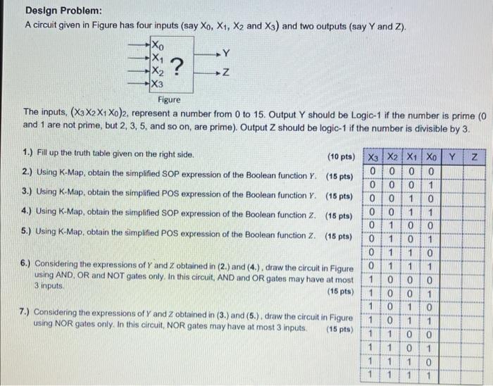
Design Problem: A circuit given in Figure has four inputs (say Xo, X1, X2 and X3) and two outputs (say Y and Z). X2 Y ? Z Figure The inputs, (X3X2X1 X0)2, represent a number from 0 to 15. Output Y should be Logic-1 if the number is prime (0 and 1 are not prime, but 2, 3, 5, and so on, are prime). Output Z should be logic-1 if the number is divisible by 3. 1.) Fill up the truth table given on the right side. (10 pts) X3 X2 X1 Xo Y Z 2.) Using K-Map, obtain the simplified SOP expression of the Boolean function Y. (15 pts) 3.) Using K-Map, obtain the simplified POS expression of the Boolean function Y. 4.) Using K-Map, obtain the simplified SOP expression of the Boolean function Z. (15 pts) 5.) Using K-Map, obtain the simplified POS expression of the Boolean function Z. (15 pts) 0 0 0 0 0 0 0 1 (15 pts) 0 0 1 0 0 0 1 1 0 1 0 0 0 1 0 1 0 1 1 0 6.) Considering the expressions of Y and Z obtained in (2.) and (4.), draw the circuit in Figure using AND, OR and NOT gates only. In this circuit, AND and OR gates may have at most 3 inputs. 7.) Considering the expressions of Y and Z obtained in (3.) and (5.). draw the circuit in Figure using NOR gates only. In this circuit, NOR gates may have at most 3 inputs. 0 1 1 1 1 0 0 0 (15 pts) 1 0 0 1 1 0 1 0 1 0 1 1 (15 pts) 1 1 0 0 1 1 0 1 1 1 1 0 1 1
Step by Step Solution
There are 3 Steps involved in it

Get step-by-step solutions from verified subject matter experts