

Question: Design the SystemVerilog module named RAMmem' for the system shown in Figure 6. The memory module has the following functionality: 1 - The module is
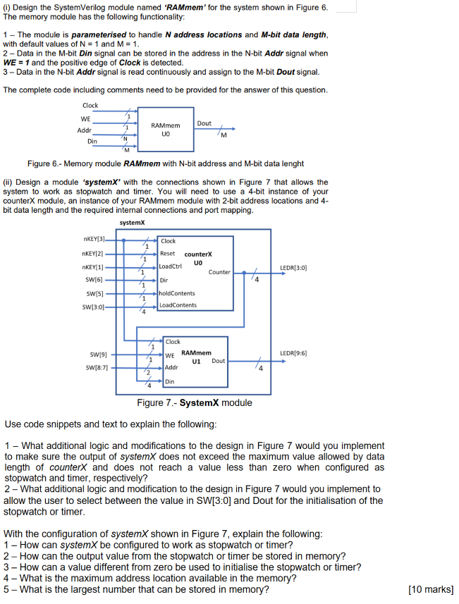
Design the SystemVerilog module named "RAMmem' for the system shown in Figure 6. The memory module has the following functionality: 1 - The module is parameterised to handle N address locations and M-bit data length, with default values of N = 1 and M = 1. 2 - Data in the M-bit Din signal can be stored in the address in the N-bit Addr signal when WE = 1 and the positive edge of Clock is detected. 3 - Data in the N-bit Addr signal is read continuously and assign to the M-bit Dout signal. The complete code including comments need to be provided for the answer of this question. Clock Dout WE Addr Din 1 'N RAMmem UO M Figure 6.- Memory module RAMmem with N-bit address and M-bit data lenght () Design a module 'systemX' with the connections shown in Figure 7 that allows the system to work as stopwatch and timer. You will need to use a 4-bit instance of your counterX module, an instance of your RAMmem module with 2-bit address locations and 4- bit data length and the required internal connections and port mapping. system/ nKEY[31- Clock 1 1 nKEY[21 KEY[1] SW[6] Reset counterX LoadCtrl UO Counter Dir LEDR(3:0) 1 1 SW[5] SW[3:01 1 holdContents LoadContents 4 SW[9] WE Clock RAMmem U1 Dout Addr LEDR(9:6) 1 to SW[8:7) 2 Din Figure 7.- SystemX module Use code snippets and text to explain the following: 1 - What additional logic and modifications to the design in Figure 7 would you implement to make sure the output of systemX does not exceed the maximum value allowed by data length of counterx and does not reach a value less than zero when configured as stopwatch and timer, respectively? 2- What additional logic and modification to the design in Figure 7 would you implement to allow the user to select between the value in SW[3:0] and Dout for the initialisation of the stopwatch or timer. With the configuration of systemX shown in Figure 7, explain the following: 1 - How can systemX be configured to work as stopwatch or timer? 2 - How can the output value from the stopwatch or timer be stored in memory? 3 - How can a value different from zero be used to initialise the stopwatch or timer? 4 - What is the maximum address location available in the memory? 5 - What is the largest number that can be stored in memory? [10 marks]
Step by Step Solution
There are 3 Steps involved in it

Get step-by-step solutions from verified subject matter experts