

Question: Digital Logic Design A sequential circuit is implemented using two T flip-flops as shown below. Derive the state diagram for the given circuit by conducting
Digital Logic Design
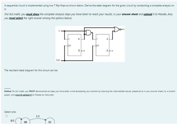
A sequential circuit is implemented using two T flip-flops as shown below. Derive the state diagram for the given circuit by conducting a complete analysis on it (For full credit, you must show the complete analysis steps you have taken to reach your results in your answer sheet and upload it to Moodle. Also, you must select the right answer among the options below) CLK The resultant state diagram for this circuit can be Notice: For full credit you MUST demonstrate all steps you have taken while developing your solution by showing the intermediate results. Please do so in your answer sheet (le, o scratch paper) and scan & upload it to Moodle as instructed Select one: 1/1 0/1 00 01
Step by Step Solution
There are 3 Steps involved in it

Get step-by-step solutions from verified subject matter experts