

Question: Enter the Ladder Logic: - Enter a Description for the device the instruction is addressed to (i.e. input devices: NO LS, NO MC PB, NO
Enter the Ladder Logic:
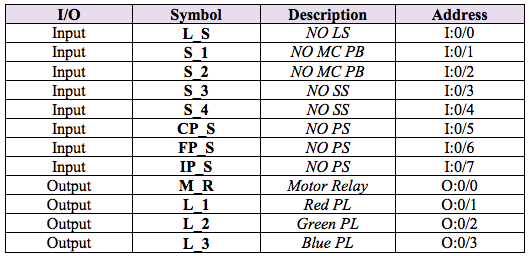
- Enter a Description for the device the instruction is addressed to (i.e. input devices: NO LS, NO MC PB, NO SS, NO PS. Output devices: Motor Relay, Red PL, Green PL, Blue PL.)
- Enter a Symbol for the device the instruction is addressed to (i.e. input devices: L_S, S_1, S_2, S_3, S_4, CP_S, FP_S, IP_S. Output devices: M_R, L_1, L_2, L_3)
Program the devices using the following symbols, descriptions, and addresses:
The program is required to operate as follows:
- The conveyor must run (M_R ON) and remain running when pushbutton S_1 is pressed and stop (M_R OFF) and remain stopped when pushbutton S_2 is pressed.
- The conveyor must temporarily stop (M_R OFF) when the limit switch L_S is activated.
- The green pilot light L_2 is to flash ON and OFF in periods of 250 milliseconds when the proximity sensor CP_S detects a part. The light is to remain flashing until the limit switch L_S is activated or pushbutton S_2 is pressed.
- The blue pilot light L_3 is to flash ON and OFF in periods of 250 milliseconds when the proximity sensor FP_S detects a part. The light is to remain flashing until the limit switch L_S is activated or pushbutton S_2 is pressed.
- When the proximity sensor IP_S is activated, a 3 second period must follow to ensure that the part clears the sensor followed by a temporary stop of the conveyor (M_R OFF) for a period of 10 seconds during which the red pilot light L_1 is to be energized. Both the green and the blue pilot lights (L_2 and L_3) must temporarily stop flashing during this 10 second period. The process must resume automatically after the 10 second period elapses.
e0123456 0 ti SPP bs-123-4 123 uu_u
Step by Step Solution
There are 3 Steps involved in it

Get step-by-step solutions from verified subject matter experts