

Question: Exercise 4. [20 marks ] In this exercise you are to construct an ALU with the following specification: - The ALU takes 3 different 32-bit
![Exercise 4. [20 marks ] In this exercise you are to](https://dsd5zvtm8ll6.cloudfront.net/si.experts.images/questions/2024/09/66f31b63a8491_29166f31b632a79b.jpg)
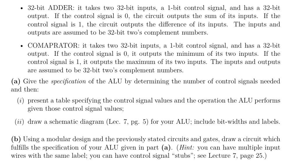
Exercise 4. [20 marks ] In this exercise you are to construct an ALU with the following specification: - The ALU takes 3 different 32-bit inputs: A, B, C; and has one 32-bit output: D. - The ALU supports 8 different operations: A+B(addition)AB(subtraction)MAX(A,B,C)MIN(A,B,C)A&B(bitwiseAND)B&C(bitwiseAND)AB(bitwiseAOR)BC(bitwiseOR) To construct this ALU you will follow a modular design. Assume you have an unlimited number of the following gates and combinational circuits at your disposal, but no others: - 2 -arity AND gate, - 2-arity OR gate, - NOT gate, - 2-way MUX, - bit-wise AND circuit: it takes two 32-bit inputs and has a 32-bit output which is the bit-wise AND of its inputs. - bit-wise OR circuit: it takes two 32-bit inputs and has a 32-bit output which is the bit-wise OR of its inputs. - 32-bit ADDER: it takes two 32-bit inputs, a 1-bit control signal, and has a 32-bit output. If the control signal is 0 , the circuit outputs the sum of its inputs. If the control signal is 1 , the circuit outputs the difference of its inputs. The inputs and outputs are assumed to be 32-bit two's complement numbers. - COMAPRATOR: it takes two 32-bit inputs, a 1-bit control signal, and has a 32-bit output. If the control signal is 0, it outputs the minimum of its two inputs. If the control signal is 1 , it outputs the maximum of its two inputs. The inputs and outputs are assumed to be 32-bit two's complement numbers. (a) Give the specification of the ALU by determining the number of control signals needed and then: (i) present a table specifying the control signal values and the operation the ALU performs given those control signal values; (ii) draw a schematic diagram (Lec. 7, pg. 5) for your ALU; include bit-widths and labels. (b) Using a modular design and the previously stated circuits and gates, draw a circuit which fulfills the specification of your ALU given in part (a). (Hint: you can have multiple input wires with the same label; you can have control signal "stubs"; see Lecture 7, page 25.)
Step by Step Solution
There are 3 Steps involved in it

Get step-by-step solutions from verified subject matter experts