

Question: Fault analysis: Consider the following five-bus power system (A-Y phase shifts are negligible. Prefault voltage is 1.08 per unit). Figure 2: A five-bus power
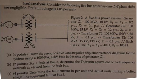
Fault analysis: Consider the following five-bus power system (A-Y phase shifts are negligible. Prefault voltage is 1.08 per unit). Figure 2: A five-bus power system. Gener- ator G1: 100 MVA, 10 kV, X1 = X2 = 0.2 p.u., Xo = 0.1 p.u. // Generator G2: 100 MVA, 15 kV, X1 p.u. // Transformer T1: 100 MVA, 10 kV/138 kV, X = 0.1 p.u. // Transformer T2: 100 MVA, 15 kV/138 kV, X = 0.1 p.u. // Each 138 kV line: X1 = X2 = 40 0, Xo = 100 0. %3D X2 = 0.2 p.u., Xo = 0.1 %3D %3D %3! (a) (4 points) Draw the zero-, positive-, and negative-sequence reactance diagrams for the system using a 100MVA, 15kV base in the zone of generator G1. (b) (2 points) For a fault at Bus 3, determine the Thvenin equivalent of each sequence network as viewed from the fault bus. (c) (4 points) Determine the fault current in per unit and actual units during a bolted single-line-to-ground fault at Bus 3.
Step by Step Solution
3.41 Rating (148 Votes )
There are 3 Steps involved in it
To address the problem well follow these steps a Draw the sequence reactance diagrams Given Data Gen... View full answer

Get step-by-step solutions from verified subject matter experts