

Question: Figure 1 shows a four - axis manipulator with one revolute joint, a prismatic joint and another two revolute joints. Note that (
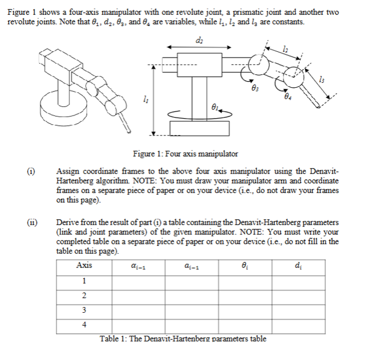
Figure shows a fouraxis manipulator with one revolute joint, a prismatic joint and another two revolute joints. Note that theta dtheta and theta are variables, while l l and l are constants.
Figure : Four axis manipulator
i Assign coordinate frames to the above four axis manipulator using the DenavitHartenberg algorithm. NOTE: You must draw your manipulator arm and coordinate frames on a separate piece of paper or on your device ie do not draw your frames on this page
ii Derive from the result of part i a table containing the DenavitHartenberg parameters link and joint parameters of the given manipulator. NOTE: You must write your completed table on a separate piece of paper or on your device ie do not fill in the table on this page
Table : The DenavitHartenberg parameters table
Step by Step Solution
There are 3 Steps involved in it
1 Expert Approved Answer
Step: 1 Unlock

Question Has Been Solved by an Expert!
Get step-by-step solutions from verified subject matter experts
Step: 2 Unlock
Step: 3 Unlock