

Question: Figure 2 below shows a sequential logic circuit constructed from two flip-flops, clocked from a single input clock signal, and two logic gates. JA QA
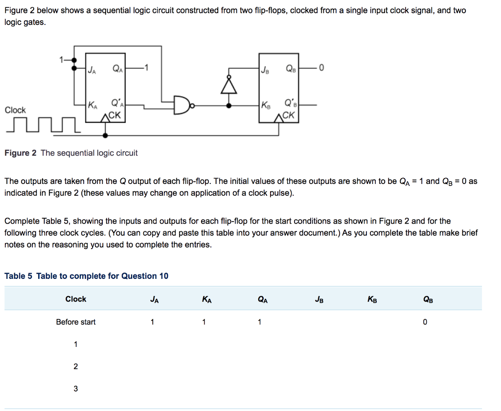
Figure 2 below shows a sequential logic circuit constructed from two flip-flops, clocked from a single input clock signal, and two logic gates. JA QA JE QB 0 KA Clock QA ACK Figure 2 The sequential logic circuit The outputs are taken from the Qoutput of each flip-flop. The initial values of these outputs are shown to be QA = 1 and QB = 0 as indicated in Figure 2 (these values may change on application of a clock pulse). Complete Table 5, showing the inputs and outputs for each flip-flop for the start conditions as shown in Figure 2 and for the following three clock cycles. (You can copy and paste this table into your answer document.) As you complete the table make brief notes on the reasoning you used to complete the entries. Table 5 Table to complete for Question 10 Clock JA KA QA KB QB Before start 1 1 1 0 1 2 3
Step by Step Solution
There are 3 Steps involved in it

Get step-by-step solutions from verified subject matter experts