

Question: Figure ( a ) shows a common - emitter amplifier and ( b ) is the equivalent circuit of the transistor. r and g m
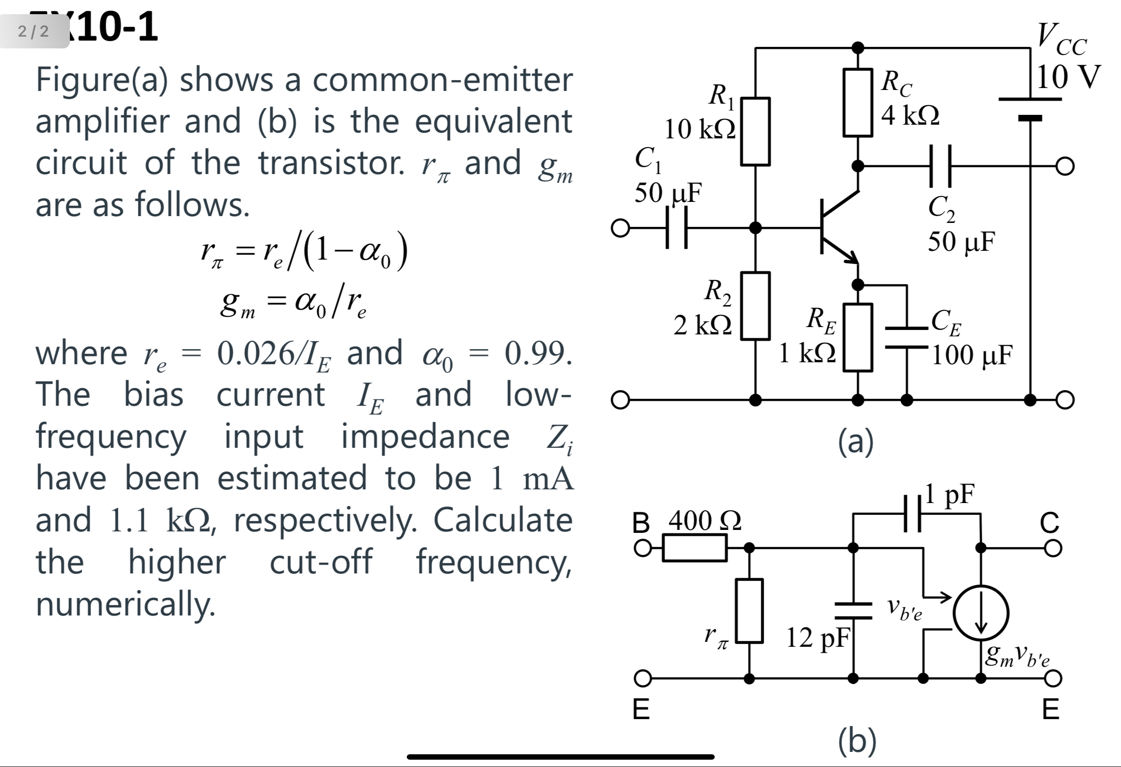
Figurea shows a commonemitter amplifier and b is the equivalent circuit of the transistor. and are as follows.
where and The bias current and lowfrequency input impedance have been estimated to be mA
a
and respectively. Calculate the higher cutoff frequency, numerically.
:
Figurea shows a commonemitter amplifier and b is the equivalent circuit of the transistor. and are as follows.
where and The bias current and lowfrequency input impedance have been estimated to be mA
a
and respectively. Calculate the higher cutoff frequency, numerically.
Step by Step Solution
There are 3 Steps involved in it
1 Expert Approved Answer
Step: 1 Unlock

Question Has Been Solved by an Expert!
Get step-by-step solutions from verified subject matter experts
Step: 2 Unlock
Step: 3 Unlock