

Question: for cisco Continuing to the previous lab ( OSPF Basic Configuration_ Lab Demo), we will assume that OSPF protocol is already configured on the routers.
for cisco
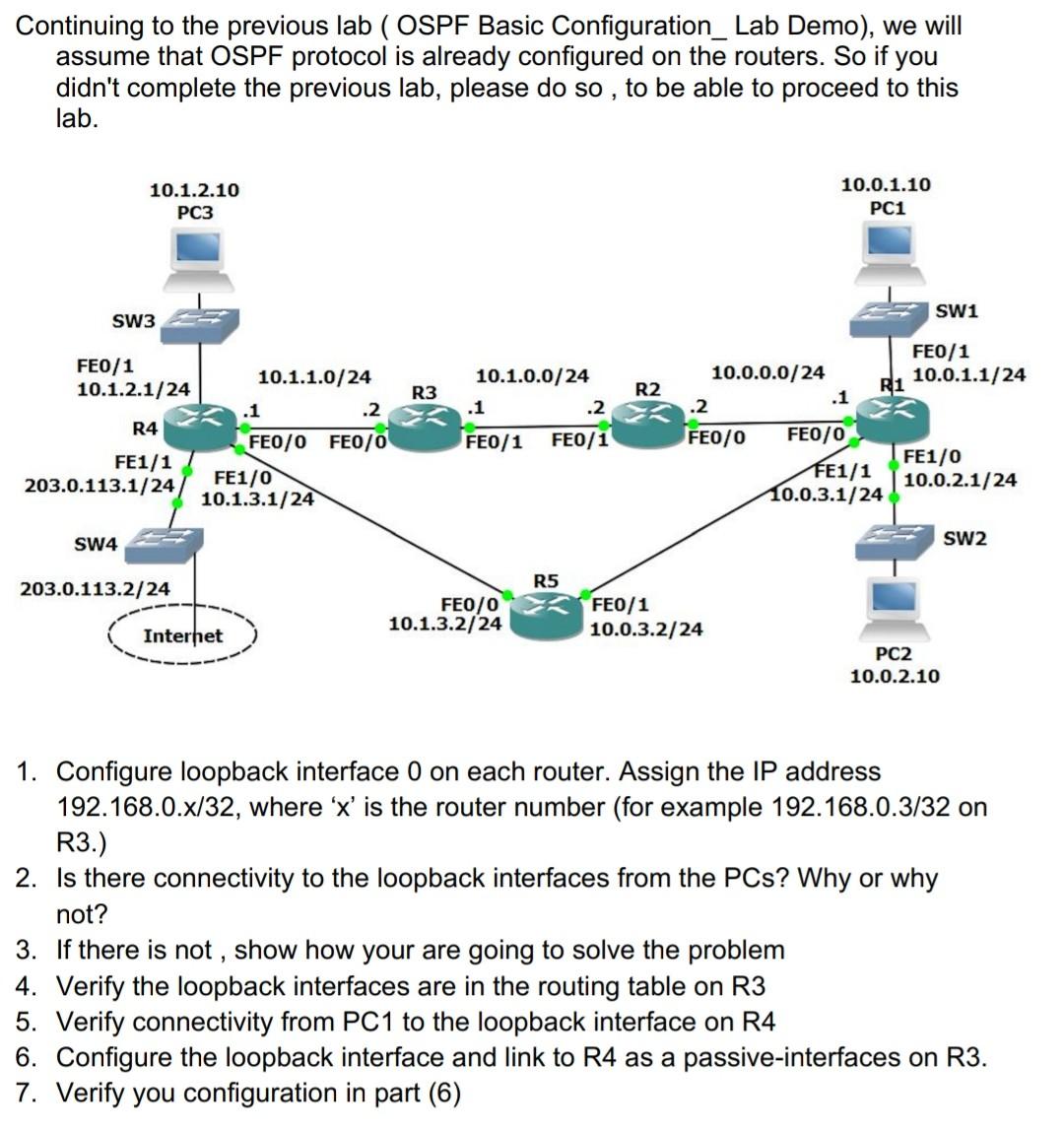
Continuing to the previous lab ( OSPF Basic Configuration_ Lab Demo), we will assume that OSPF protocol is already configured on the routers. So if you didn't complete the previous lab, please do so, to be able to proceed to this lab. 10.1.2.10 PC3 10.0.1.10 PC1 SW1 SW3 FE0/1 10.1.2.1/24 10.1.1.0/24 .1 .2 R3 R2 10.1.0.0/24 .1 .2 FE0/1 FE0/1 R4 FEO/1 10.0.0.0/24 R1 10.0.1.1/24 .1 .2 FE0/0 FE0/0 FE1/0 FE1/1 10.0.2.1/24 10.0.3.1/24 FE1/1 203.0.113.1/24 FEO/O FE0/0 FE1/0 10.1.3.1/24 SW4 SW2 R5 203.0.113.2/24 FEO/0 10.1.3.2/24 FE0/1 10.0.3.2/24 Internet PC2 10.0.2.10 1. Configure loopback interface 0 on each router. Assign the IP address 192.168.0.x/32, where 'x' is the router number (for example 192.168.0.3/32 on R3.) 2. Is there connectivity to the loopback interfaces from the PCs? Why or why not? 3. If there is not , show how your are going to solve the problem 4. Verify the loopback interfaces are in the routing table on R3 5. Verify connectivity from PC1 to the loopback interface on R4 6. Configure the loopback interface and link to R4 as a passive-interfaces on R3. 7. Verify you configuration in part (6) Continuing to the previous lab ( OSPF Basic Configuration_ Lab Demo), we will assume that OSPF protocol is already configured on the routers. So if you didn't complete the previous lab, please do so, to be able to proceed to this lab. 10.1.2.10 PC3 10.0.1.10 PC1 SW1 SW3 FE0/1 10.1.2.1/24 10.1.1.0/24 .1 .2 R3 R2 10.1.0.0/24 .1 .2 FE0/1 FE0/1 R4 FEO/1 10.0.0.0/24 R1 10.0.1.1/24 .1 .2 FE0/0 FE0/0 FE1/0 FE1/1 10.0.2.1/24 10.0.3.1/24 FE1/1 203.0.113.1/24 FEO/O FE0/0 FE1/0 10.1.3.1/24 SW4 SW2 R5 203.0.113.2/24 FEO/0 10.1.3.2/24 FE0/1 10.0.3.2/24 Internet PC2 10.0.2.10 1. Configure loopback interface 0 on each router. Assign the IP address 192.168.0.x/32, where 'x' is the router number (for example 192.168.0.3/32 on R3.) 2. Is there connectivity to the loopback interfaces from the PCs? Why or why not? 3. If there is not , show how your are going to solve the problem 4. Verify the loopback interfaces are in the routing table on R3 5. Verify connectivity from PC1 to the loopback interface on R4 6. Configure the loopback interface and link to R4 as a passive-interfaces on R3. 7. Verify you configuration in part (6)
Step by Step Solution
There are 3 Steps involved in it

Get step-by-step solutions from verified subject matter experts