

Question: For the 8-bit add/subtract circuit created in hw7, write a Verilog AND a VHDL testbench. Test ONLY the following input vectors: AS Sel Result Cout
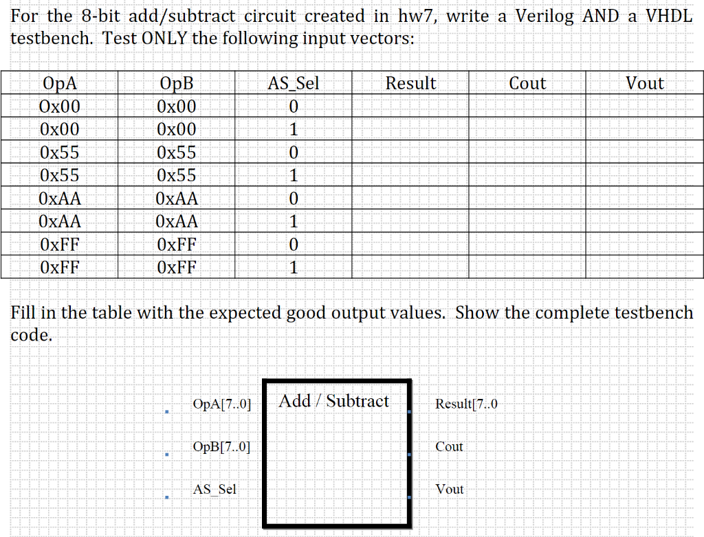
For the 8-bit add/subtract circuit created in hw7, write a Verilog AND a VHDL testbench. Test ONLY the following input vectors: AS Sel Result Cout Vout OpA Ox00 Ox00 Ox55 Ox55 OxAA OxAA OxFF OxFF OpB Ox00 Ox00 Ox55 0x55 OxAA OxAA OxFF OxFF Fill in the table with the expected good output values. Show the complete testbench code. OpA 7..01 Add Subtract Result[7..0 OpB[7..0] Cout AS_Sel Vout For the 8-bit add/subtract circuit created in hw7, write a Verilog AND a VHDL testbench. Test ONLY the following input vectors: AS Sel Result Cout Vout OpA Ox00 Ox00 Ox55 Ox55 OxAA OxAA OxFF OxFF OpB Ox00 Ox00 Ox55 0x55 OxAA OxAA OxFF OxFF Fill in the table with the expected good output values. Show the complete testbench code. OpA 7..01 Add Subtract Result[7..0 OpB[7..0] Cout AS_Sel Vout
Step by Step Solution
There are 3 Steps involved in it

Get step-by-step solutions from verified subject matter experts