

Question: For the system shown above: Entire system is at Steady State Instrument Locations shown as: TI ( temp ) ; FI ( flow ) ;
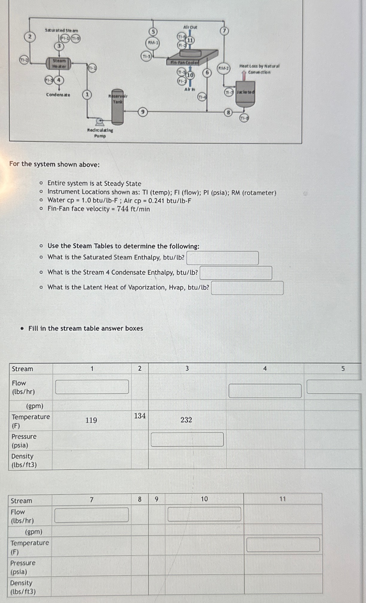
For the system shown above:
Entire system is at Steady State
Instrument Locations shown as: TI temp; FI flow; PI psia; RM rotameter
Water ; Air
FinFan face velocity
Use the Steam Tables to determine the following:
What is the Saturated Steam Enthalpy, btulb
What is the Stream Condensate Enthalpy, btulb
What is the Latent Heat of Vaporization, Hvap, btulb:
Fill in the stream table answer boxes
tableStreamtableFlowlbshrgpmtableTemperatureFtablePressurepsiatableDensitylbsft
tableStreamtableFlowlbshrgpmtableTemperatureFtablePressurepsiatableDensitybsftCalculate and Enter the following Heat Duties
REMEMBER TO ENTER THE CORRECT SIGN HEAT ADDED, HEAT REMOVED
ShellTube exchanger waterside duty, btuhr
FinFan exchanger waterside duty, btuhr
Jacketed exchanger waterside duty, btuhr
Reservoir Tank waterside duty, btuhr
Uninsulated pipingequipment waterside duty, btuhr
ShellTube exchanger
The duty of this exchanger adheres to the standard heat transfer equation
Ao ; where is the log mean temperature difference,
The total exchanger outside tube area, Ao is
What is the
What is the overall heat transfer coefficient, Uo btuhrftF
Step by Step Solution
There are 3 Steps involved in it
1 Expert Approved Answer
Step: 1 Unlock

Question Has Been Solved by an Expert!
Get step-by-step solutions from verified subject matter experts
Step: 2 Unlock
Step: 3 Unlock