

Question: I can't access to PSIM to simulate this question. Please simulate according to the question. Thank you! Figure 3 . 6 . The Buck converter
I can't access to PSIM to simulate this question. Please simulate according to the question. Thank you!
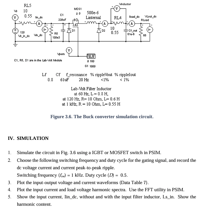
Figure The Buck converter simulation circuit.
Simulate the circuit in Fig. using a IGBT or MOSFET switch in PSIM.
Choose the following switching frequency and duty cycle for the gating signal, and record the
dc voltage current and current peaktopeak ripple.
Switching frequency fsw kHz Duty cycle D
Plot the inputoutput voltage and current waveforms Data Table
Plot the input current and load voltage harmonic spectra. Use the FFT utility in PSIM.
Show the input current, Iindc without and with the input filter inductor, Lsin Show the harmonic content.
Table Converter Simulation Results PSIM
Step by Step Solution
There are 3 Steps involved in it
1 Expert Approved Answer
Step: 1 Unlock

Question Has Been Solved by an Expert!
Get step-by-step solutions from verified subject matter experts
Step: 2 Unlock
Step: 3 Unlock