

Question: Implement the required ALU. Use 32-bit registers for the inputs (X and Y). Use a 4-bit register as the operation selector (Op). Use a 32-bit
Implement the required ALU. Use 32-bit registers for the inputs (X and Y). Use a 4-bit register as the operation selector (Op). Use a 32-bit probe to monitor the R output. Use individual 1-bit probes to monitor the Status Flag outputs.
Please implement this circuit on software, preferably logisim.
WHAT THE ALU MUST DO / INTERFACE:
This is from notes what it should contain and abstractly look like:
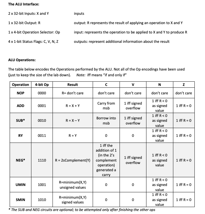
The ALU Interface: 2 x 32-bit Inputs:X and Y inputs 1 x 32-bit Output: R output: R represents the result of applying an operation to X and Y input: represents the operation to be applied to X and Y to produce R 1 x 4-bit Operation Selector: Op 4x 1-bit Status Flags: C, V, N, Z outputs: represent additional information about the result ALU Operations: The table below encodes the Operations performed by the ALU. Not all of the Op encodings have been used (just to keep the size of the lab down). Note: iff means "if and only if" z don't care 1 iff R = 0 1 iff R = 0 RY 1 iff R = 0 Operation 4-bit Op Result V N NOP 0000 R= don't care don't care don't care don't care Carry from 1 iff RO ADD 1 iff signed 0001 R=X+Y msb as signed overflow value 1 iff RO Borrow into SUB 0010 1 iff signed R = X-Y as signed msb overflow value 1 iff R
Step by Step Solution
There are 3 Steps involved in it

Get step-by-step solutions from verified subject matter experts