

Question: In a system where the liquid level is controlled, the system's inlet is shown by R(s) and its output by C(s). R(s) C(s) Ge(s) G(s)
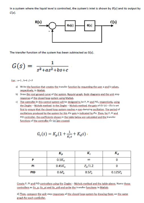
In a system where the liquid level is controlled, the system's inlet is shown by R(s) and its output by C(s). R(s) C(s) Ge(s) G(s) The transfer function of the system has been subtracted as G(s). G(s) = 1 sa+as+bs+c For: -1, 5-6,0-7 a) Write the function that creates the transfer function by requesting the user a and b values respectively, in Matlab b) Draw the rootEtound curve of the system Nyauist och Bodesivecams and the unit step response of the closed loop system using Matlab. c) The controller in this control system will be designed to be P, Pl and PID, respectively, using the Ziegler - Nichols method. In the Ziegler - Nichols method, the gain of GC (s) = Ka is set first to easure that the closed logo system reaches a non-damping oscillation. The period of oscillations produced by the system for this Ka gain is indicated by Pa. Then, fr P. Pl and PID gootroller the coefficients shown in the table below are salculated and the transfer functions of the controller Gels) are created Ge(s) = K,(1+*+ Kd8) Kis K P 00 0 PI 0.5K 0.45K 0.6 Pa 0 Pa/1.2 0.5P PID 0.125P Create P.Pl and PID controllers using the Ziegler - Nichols method and the table above, Name these controllers as G.R. Gs..el and Gaid and write the transfer functions in Matlab. d) Then, compare the unit step responses of the closed loop system by drawing them on the same graph for each controller In a system where the liquid level is controlled, the system's inlet is shown by R(s) and its output by C(s). R(s) C(s) Ge(s) G(s) The transfer function of the system has been subtracted as G(s). G(s) = 1 sa+as+bs+c For: -1, 5-6,0-7 a) Write the function that creates the transfer function by requesting the user a and b values respectively, in Matlab b) Draw the rootEtound curve of the system Nyauist och Bodesivecams and the unit step response of the closed loop system using Matlab. c) The controller in this control system will be designed to be P, Pl and PID, respectively, using the Ziegler - Nichols method. In the Ziegler - Nichols method, the gain of GC (s) = Ka is set first to easure that the closed logo system reaches a non-damping oscillation. The period of oscillations produced by the system for this Ka gain is indicated by Pa. Then, fr P. Pl and PID gootroller the coefficients shown in the table below are salculated and the transfer functions of the controller Gels) are created Ge(s) = K,(1+*+ Kd8) Kis K P 00 0 PI 0.5K 0.45K 0.6 Pa 0 Pa/1.2 0.5P PID 0.125P Create P.Pl and PID controllers using the Ziegler - Nichols method and the table above, Name these controllers as G.R. Gs..el and Gaid and write the transfer functions in Matlab. d) Then, compare the unit step responses of the closed loop system by drawing them on the same graph for each controller
Step by Step Solution
There are 3 Steps involved in it

Get step-by-step solutions from verified subject matter experts