

Question: LEVEL 3 DESIGN LOADS - WEST WING LOAD SDL LIVE LIVE CONCENTRICA PARTITIONS kN/m2 PSF DENOTED ON PLAN AREA kN/m2 PSF kN/m2 PSF KN KIPS
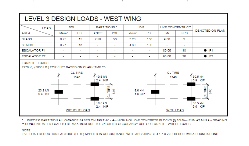
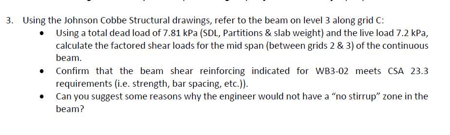

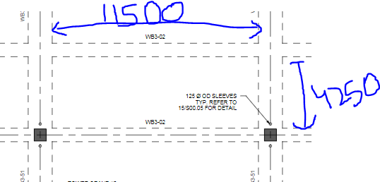
LEVEL 3 DESIGN LOADS - WEST WING LOAD SDL LIVE LIVE CONCENTRICA PARTITIONS kN/m2 PSF DENOTED ON PLAN AREA kN/m2 PSF kN/m2 PSF KN KIPS 0.75 2.50 53 7.20 150 9.00 2 SLABS STAIRS ESCALATOR P1 15 15 0.75 4.80 100 80.00 18 P1 ESCALATOR P2 90.00 20 P2 FORKLIFT LOADS: 2270 Kg (5000 LB.) FORKLIFT BASED ON CLARK TMX 25 CL TIRE 1340 10.6 kN 2.4 KIP CL TIRE 1340 30.5 KN 6.9 KIP 23.8 kN 5.4 KIP CL TIRE 846 8.6 kN 1.9 KIP CL TIRE 846 10.6 KN 2.4 KIP 30.5 kN 6.9 KIP WITHOUT LOAD WITH LOAD UNIFORM PARTITION ALLOWANCE BASED ON 190 THK x 4m HIGH HOLLOW CONCRETE BLOCKS @ 10kN/m RUN AT MIN 4m SPACING ** CONCENTRATED LOAD TO BE MAXIMUM DUE TO SPECIFIED OCCUPANCY USE OR FORKLIFT WHEEL LOADS NOTE: LIVE LOAD REDUCTION FACTORS (LLRF) APPLIED IN ACCORDANCE WITH ABC 2006 (CL 4.1.5.92) FOR COLUMN & FOUNDATIONS 3. Using the Johnson Cobbe Structural drawings, refer to the beam on level 3 along grid C: Using a total dead load of 7.81 kPa (SDL, Partitions & slab weight) and the live load 7.2 kPa, calculate the factored shear loads for the mid span (between grids 2 & 3) of the continuous beam. Confirm that the beam shear reinforcing indicated for WB3-02 meets CSA 23.3 requirements (i.e. strength, bar spacing, etc.)). Can you suggest some reasons why the engineer would not have a no stirrup zone in the beam? WB3-01 875x650 360 O.C. REM 3-30M 4-30M B T 5-25M 4-25M TUL+ 5-25M TLL WB3-02 675x650 10M T 1 10 7 300 0%. L 10 @ 300 .c. 350 0.c. REM 4-25M 4-25M B T 5-25M 4-25M TUL+ 5-25M TLL 7 WB3-03 875x650 10M 11 300 O.O.F.L. ISO W63-02 125 O OD SLEEVES TYP. REFER TO 15/500.05 FOR DETAIL 4250 W63-02 HH 3-51 LEVEL 3 DESIGN LOADS - WEST WING LOAD SDL LIVE LIVE CONCENTRICA PARTITIONS kN/m2 PSF DENOTED ON PLAN AREA kN/m2 PSF kN/m2 PSF KN KIPS 0.75 2.50 53 7.20 150 9.00 2 SLABS STAIRS ESCALATOR P1 15 15 0.75 4.80 100 80.00 18 P1 ESCALATOR P2 90.00 20 P2 FORKLIFT LOADS: 2270 Kg (5000 LB.) FORKLIFT BASED ON CLARK TMX 25 CL TIRE 1340 10.6 kN 2.4 KIP CL TIRE 1340 30.5 KN 6.9 KIP 23.8 kN 5.4 KIP CL TIRE 846 8.6 kN 1.9 KIP CL TIRE 846 10.6 KN 2.4 KIP 30.5 kN 6.9 KIP WITHOUT LOAD WITH LOAD UNIFORM PARTITION ALLOWANCE BASED ON 190 THK x 4m HIGH HOLLOW CONCRETE BLOCKS @ 10kN/m RUN AT MIN 4m SPACING ** CONCENTRATED LOAD TO BE MAXIMUM DUE TO SPECIFIED OCCUPANCY USE OR FORKLIFT WHEEL LOADS NOTE: LIVE LOAD REDUCTION FACTORS (LLRF) APPLIED IN ACCORDANCE WITH ABC 2006 (CL 4.1.5.92) FOR COLUMN & FOUNDATIONS 3. Using the Johnson Cobbe Structural drawings, refer to the beam on level 3 along grid C: Using a total dead load of 7.81 kPa (SDL, Partitions & slab weight) and the live load 7.2 kPa, calculate the factored shear loads for the mid span (between grids 2 & 3) of the continuous beam. Confirm that the beam shear reinforcing indicated for WB3-02 meets CSA 23.3 requirements (i.e. strength, bar spacing, etc.)). Can you suggest some reasons why the engineer would not have a no stirrup zone in the beam? WB3-01 875x650 360 O.C. REM 3-30M 4-30M B T 5-25M 4-25M TUL+ 5-25M TLL WB3-02 675x650 10M T 1 10 7 300 0%. L 10 @ 300 .c. 350 0.c. REM 4-25M 4-25M B T 5-25M 4-25M TUL+ 5-25M TLL 7 WB3-03 875x650 10M 11 300 O.O.F.L. ISO W63-02 125 O OD SLEEVES TYP. REFER TO 15/500.05 FOR DETAIL 4250 W63-02 HH 3-51
Step by Step Solution
There are 3 Steps involved in it

Get step-by-step solutions from verified subject matter experts