

Question: need urgent, as fast as possible A process that involves two electrically heated tanks in series is shown in the diagram below. The inlet temperature
 need urgent, as fast as possible
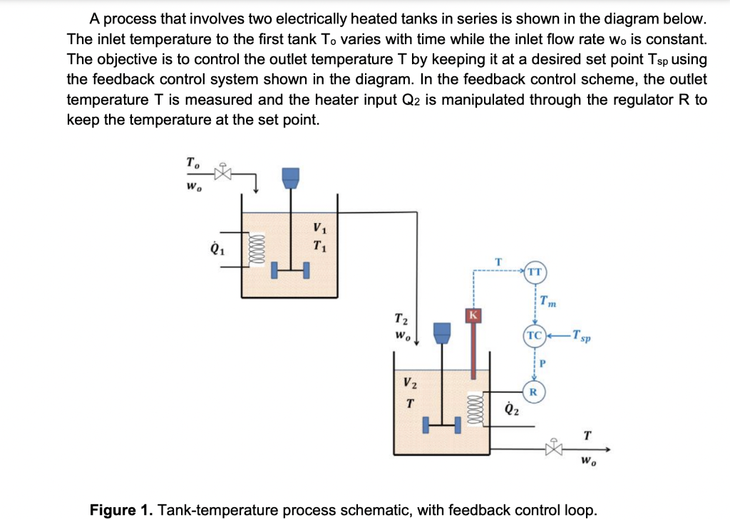
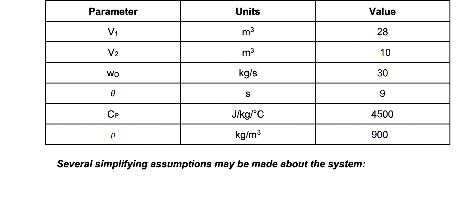
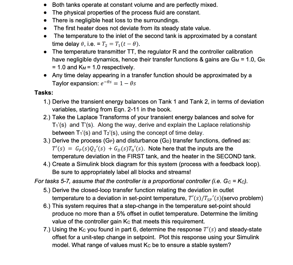
A process that involves two electrically heated tanks in series is shown in the diagram below. The inlet temperature to the first tank To varies with time while the inlet flow rate wo is constant. The objective is to control the outlet temperature T by keeping it at a desired set point Tsp using the feedback control system shown in the diagram. In the feedback control scheme, the outlet temperature T is measured and the heater input Q2 is manipulated through the regulator R to keep the temperature at the set point. T. W. V1 T1 01 000000 TI T T2 wo TC Tsp P V2 T Q2 W. Figure 1. Tank-temperature process schematic, with feedback control loop. Parameter Units Value V1 m3 28 V2 m3 10 Wo kg/s 30 S 9 Cp J/kg/C 4500 kg/m3 900 Several simplifying assumptions may be made about the system: O . . . Both tanks operate at constant volume and are perfectly mixed. The physical properties of the process fluid are constant. There is negligible heat loss to the surroundings. The first heater does not deviate from its steady state value. The temperature to the inlet of the second tank is approximated by a constant time delay e, i.e. = T2 = Ti(t 0). The temperature transmitter TT, the regulator R and the controller calibration have negligible dynamics, hence their transfer functions & gains are GM = 1.0, GR = 1.0 and KM = 1.0 respectively. Any time delay appearing in a transfer function should be approximated by a Taylor expansion: e-os = 1 - Os Tasks: 1.) Derive the transient energy balances on Tank 1 and Tank 2, in terms of deviation variables, starting from Egn. 2-11 in the book. 2.) Take the Laplace Transforms of your transient energy balances and solve for Ti'(s) and T'(s). Along the way, derive and explain the Laplace relationship between T1'(s) and T2'(s), using the concept of time delay. 3.) Derive the process (GP) and disturbance (GD) transfer functions, defined as: T'(s) = Gp(s)Qz'(s) + Gp(s)T,'(s). Note here that the inputs are the temperature deviation in the FIRST tank, and the heater in the SECOND tank. 4.) Create a Simulink block diagram for this system (process with a feedback loop). Be sure to appropriately label all blocks and streams! For tasks 5-7, assume that the controller is a proportional controller (i.e. Gc = Kc). 5.) Derive the closed-loop transfer function relating the deviation in outlet temperature to a deviation in set-point temperature, T'(s)/Tsp (s)(servo problem) 6.) This system requires that a step-change in the temperature set-point should produce no more than a 5% offset in outlet temperature. Determine the limiting value of the controller gain Kc that meets this requirement. 7.) Using the Kc you found in part 6, determine the response T'(s) and steady-state offset for a unit-step change in setpoint. Plot this response using your Simulink model. What range of values must Kc be to ensure a stable system
Step by Step Solution
There are 3 Steps involved in it

Get step-by-step solutions from verified subject matter experts