

Question: P 1 0 . 3 For the circuit shown in Fig. P 1 0 . 3 . Assume ( mathrm { M }
P
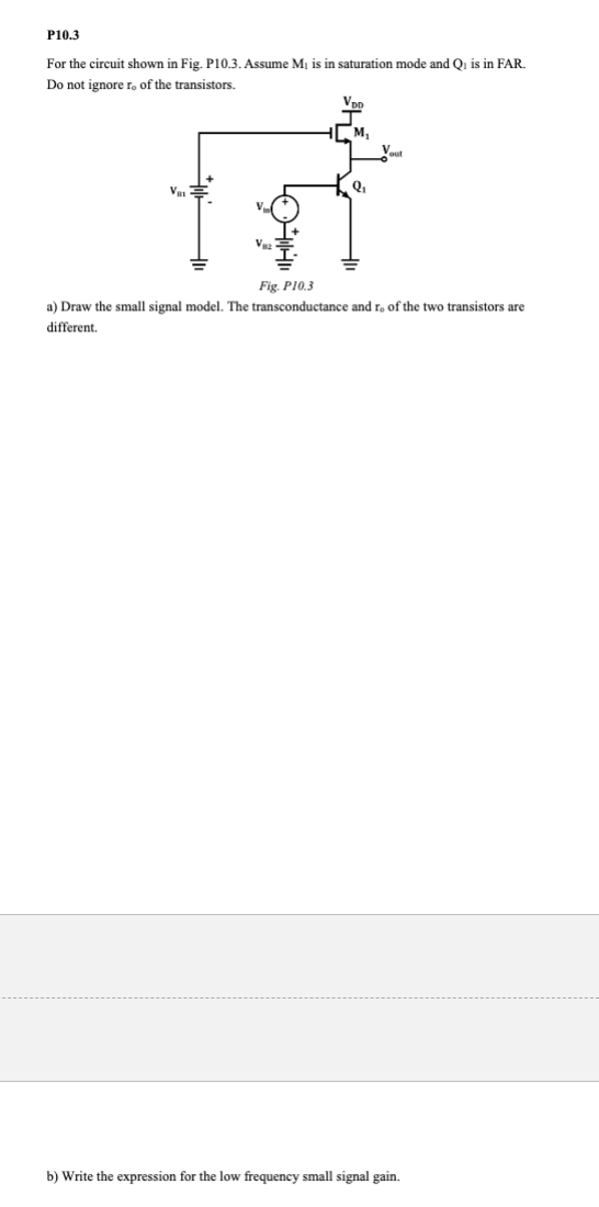
For the circuit shown in Fig. P Assume mathrmM is in saturation mode and mathrmQ is in FAR. Do not ignore mathrmrmathrmo of the transistors.
a Draw the small signal model. The transconductance and mathrmrmathrmo of the two transistors are different.
b Write the expression for the low frequency small signal gain.
Step by Step Solution
There are 3 Steps involved in it
1 Expert Approved Answer
Step: 1 Unlock

Question Has Been Solved by an Expert!
Get step-by-step solutions from verified subject matter experts
Step: 2 Unlock
Step: 3 Unlock