

Question: Packet Tracer - Configure End Devices Objectives Configure various end devices in Packet Tracer. Background / Scenario In this activity, you will construct a simple
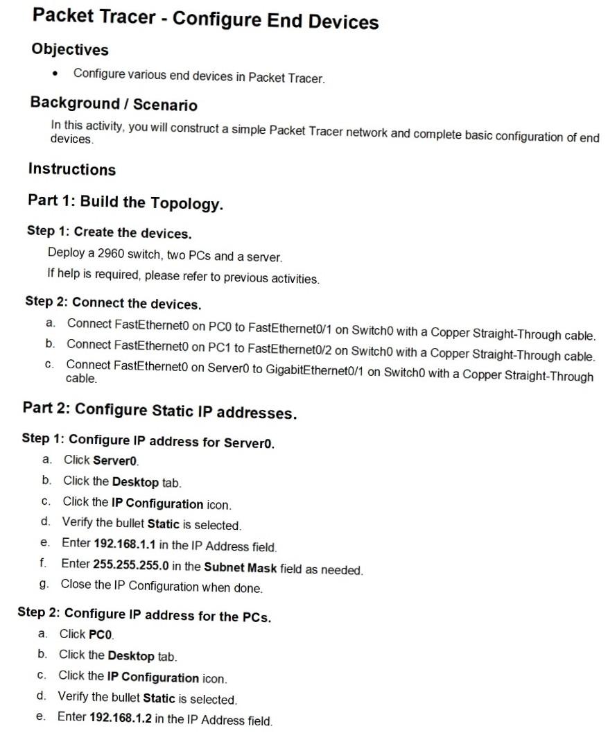
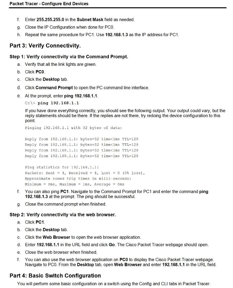
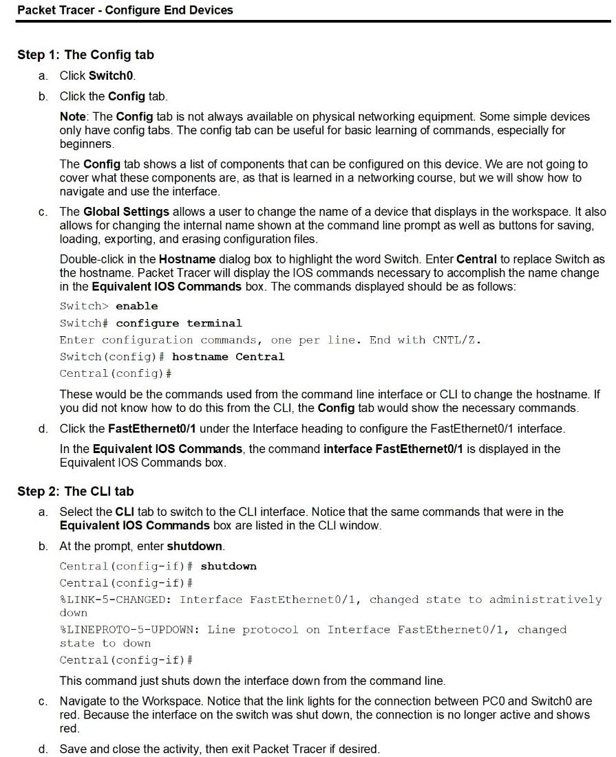
Packet Tracer - Configure End Devices Objectives Configure various end devices in Packet Tracer. Background / Scenario In this activity, you will construct a simple Packet Tracer network and complete basic configuration of end devices Instructions Part 1: Build the Topology. Step 1: Create the devices. Deploy a 2960 switch, two PCs and a server. If help is required, please refer to previous activities. Step 2: Connect the devices. a. Connect FastEtherneto on PCO to FastEthernet0/1 on Switch0 with a Copper Straight-Through cable. b. Connect FastEtherneto on PC1 to FastEthernet0/2 on Switch0 with a Copper Straight-Through cable. C. Connect FastEtherneto on Server to GigabitEthernet0/1 on Switch0 with a Copper Straight-Through cable. Part 2: Configure Static IP addresses. Step 1: Configure IP address for Servero. a. Click Server b. Click the Desktop tab. C. Click the IP Configuration icon. d. Verify the bullet Static is selected. e. Enter 192.168.1.1 in the IP Address field. f. Enter 255.255.255.0 in the Subnet Mask field as needed. g. Close the IP Configuration when done. a. Step 2: Configure IP address for the PCs. Click PCO. b. Click the Desktop tab. C Click the IP Configuration icon. d. Verify the bullet Static is selected. e. Enter 192.168.1.2 in the IP Address field. Packet Tracer - Configure End Devices f. Enter 255.255.255.0 in the Subnet Mask field as needed. g. Close the IP Configuration when done for PCO. h. Repeat the same procedure for PC1. Use 192.168.1.3 as the IP address for PC1. Part 3: Verify Connectivity. C. Step 1: Verify connectivity via the Command Prompt. a. Verify that all the link lights are green. b. Click PCO. Click the Desktop tab. d. Click Command Prompt to open the PC command line interface. e. At the prompt, enter ping 192.168.1.1. C:\> ping 192.168.1.1 If you have done everything correctly, you should see the following output. Your output could vary, but the reply statements should be there. If the replies are not there, try redoing the device configuration to this point. Pinging 192.168.1.1 with 32 bytes of data: Reply from 192.168.1.1: bytes=32 time enable Switch# configure terminal Enter configuration commands, one per line. End with CNTL/Z. Switch(config)# hostname Central Central (config)# These would be the commands used from the command line interface or CLI to change the hostname. If you did not know how to do this from the CLI, the Config tab would show the necessary commands. d. Click the FastEthernet0/1 under the Interface heading to configure the FastEthernet0/1 interface. In the Equivalent Ios Commands, the command interface FastEthernet0/1 is displayed in the Equivalent IOS Commands box. a. Step 2: The CLI tab Select the CLI tab to switch to the CLI interface. Notice that the same commands that were in the Equivalent IOS Commands box are listed in the CLI window. b. At the prompt, enter shutdown. Central (config-if)# shutdown Central (config-if)# LINK-5-CHANGED: Interface FastEthernet0/1, changed state to administratively down 8LINEPROTO-5-UPDOWN: Line protocol on Interface FastEthernet0/1, changed state to down Central (config-if)# This command just shuts down the interface down from the command line. c. Navigate to the Workspace. Notice that the link lights for the connection between PCO and Switch0 are red. Because the interface on the switch was shut down, the connection is no longer active and shows red. d. Save and close the activity, then exit Packet Tracer if desired
Step by Step Solution
There are 3 Steps involved in it

Get step-by-step solutions from verified subject matter experts