

Question: Part 2 - Mux and Adder - Verilog and Simulation ( 4 0 pts ) Using the edaplayground website, in the file design. sv instantiate
Part Mux and Adder Verilog and Simulation pts
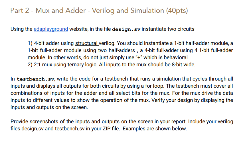
Using the edaplayground website, in the file design. sv instantiate two circuits
bit adder using structural verilog. You should instantiate a bit halfadder module, a
bit fulladder module using two halfadders, a bit fulladder using bit fulladder
module. In other words, do not just simply use which is behavioral
: mux using ternary logic. All inputs to the mux should be bit wide.
In
testbench.sv write the code for a testbench that runs a simulation that cycles through all
inputs and displays all outputs for both circuits by using a for loop. The testbench must cover all
combinations of inputs for the adder and all select bits for the mux. For the mux drive the data
inputs to different values to show the operation of the mux. Verify your design by displaying the
inputs and outputs on the screen.
Provide screenshots of the inputs and outputs on the screen in your report. Include your verilog
files
design.sv and
testbench.sv in your ZIP file. Examples are shown below. # KERNEL: Start Verifying Adder
# KERNEL: cin:
# KERNEL: cin:
# KERNEL: cin:
# KERNEL: cin:
# KERNEL: cin:
# KERNEL: cin:
# KERNEL: Start Verifying Mux
# KERNEL: sel: i: i: y:
# KERNEL: sel: i: i: y:
# KERNEL: sel: i: i: y:
# KERNEL: sel: i: i: y:
# KERNEL: sel: i: i: y:
# KERNEL: sel: i: i: y:
# KERNEL: sel: i: i: y:
# KERNEL: sel: i: i: y:
Can you write the verilog code about this question and have output like this example please
Step by Step Solution
There are 3 Steps involved in it
1 Expert Approved Answer
Step: 1 Unlock

Question Has Been Solved by an Expert!
Get step-by-step solutions from verified subject matter experts
Step: 2 Unlock
Step: 3 Unlock