

Question: Part - B: The Inverting Voltage Amplifier Background Information: The inverting voltage amplifier is based on parallel - parallel negative feedback. This amplifier exhibits modest
PartB: The Inverting Voltage Amplifier
Background Information:
The inverting voltage amplifier is based on parallelparallel negative feedback. This amplifier exhibits modest input impedance, low output impedance, and stable inverting voltage gain. The voltage gain is set by the two feedback resistors, Ri and Rf
Experimental Procedure:
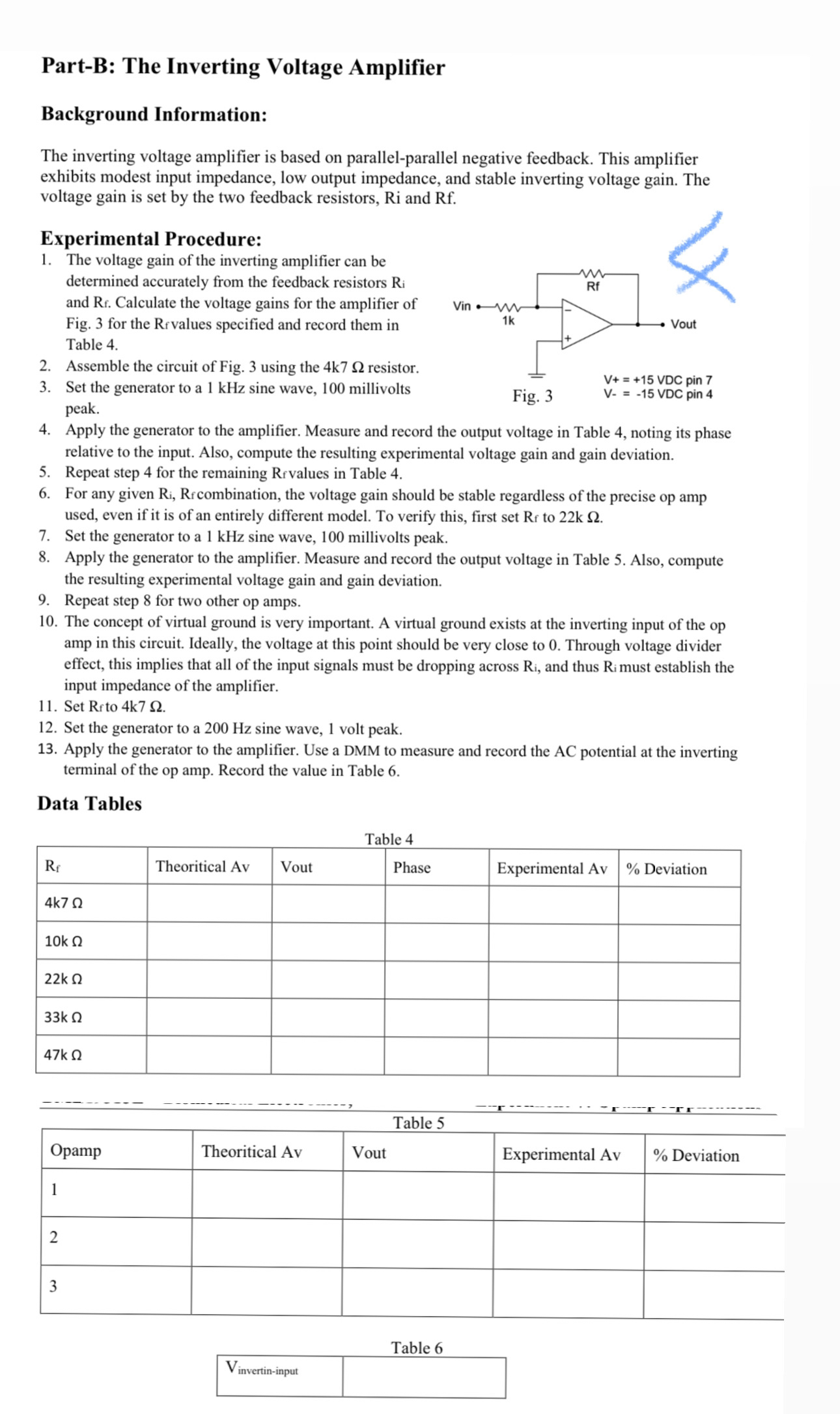
The voltage gain of the inverting amplifier can be determined accurately from the feedback resistors and Calculate the voltage gains for the amplifier of Fig. for the Revalues specified and record them in Table
Assemble the circuit of Fig. using the resistor.
Set the generator to a kHz sine wave, millivolts peak.
Apply the generator to the amplifier. Measure and record the output voltage in Table noting its phase relative to the input. Also, compute the resulting experimental voltage gain and gain deviation.
Repeat step for the remaining Rfvalues in Table
For any given combination, the voltage gain should be stable regardless of the precise op amp used, even if it is of an entirely different model. To verify this, first set to
Set the generator to a kHz sine wave, millivolts peak.
Apply the generator to the amplifier. Measure and record the output voltage in Table Also, compute the resulting experimental voltage gain and gain deviation.
Repeat step for two other op amps.
The concept of virtual ground is very important. A virtual ground exists at the inverting input of the op amp in this circuit. Ideally, the voltage at this point should be very close to Through voltage divider effect, this implies that all of the input signals must be dropping across and thus must establish the input impedance of the amplifier.
Set Re to
Set the generator to a Hz sine wave, volt peak.
Apply the generator to the amplifier. Use a DMM to measure and record the AC potential at the inverting terminal of the op amp. Record the value in Table
Data Tables
Table
tableTheoritical AvVout,Phase,Experimental Av Deviation
tableOpampTheoritical AvVout,Experimental Av Deviation
Table
table Opamp modle
Step by Step Solution
There are 3 Steps involved in it
1 Expert Approved Answer
Step: 1 Unlock

Question Has Been Solved by an Expert!
Get step-by-step solutions from verified subject matter experts
Step: 2 Unlock
Step: 3 Unlock