

Question: Compare the angles and line flows between the Example 6_17 case and results shown in Tables 6.6, 6.7, and 6.8. Table 6.6 Table 6.7 Table
Compare the angles and line flows between the Example 6_17 case and results shown in Tables 6.6, 6.7, and 6.8.
Table 6.6
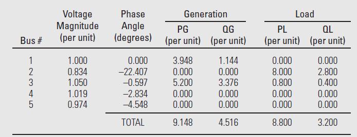
Table 6.7
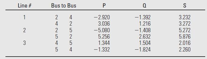
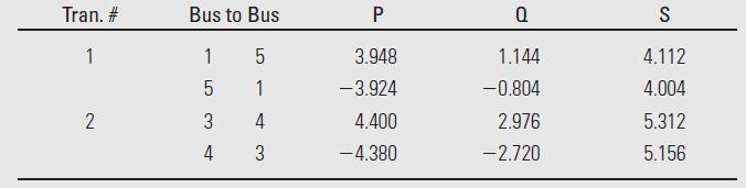
Table 6.8
Example 6_17
Determine the dc power flow solution for the five bus system from Example 6.9.
Example 6.9
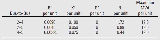
Figure 6.2 shows a single-line diagram of a five-bus power system. Input data are given in Tables 6.1, 6.2, and 6.3. As shown in Table 6.1, bus 1, to which a generator is connected, is the swing bus. Bus 3, to which a generator and a load are connected, is a voltage-controlled bus. Buses 2, 4, and 5 are load buses. Note that the loads at buses 2 and 3 are inductive since \(\mathrm{Q}_{2}=-\mathrm{Q}_{\mathrm{L} 2}=-2.8\) and \(-\mathrm{Q}_{\mathrm{L} 3}=\) -0.4 are negative.
For each bus \(k\), determine which of the variables \(\mathrm{V}_{k}, \delta_{k}, \mathrm{P}_{k}\), and \(\mathrm{Q}_{k}\) are input data and which are unknowns. Also, compute the elements of the second row of \(\boldsymbol{Y}_{\text {bus }}\).
Figure 6.2
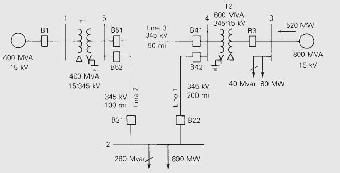
Table 6.1
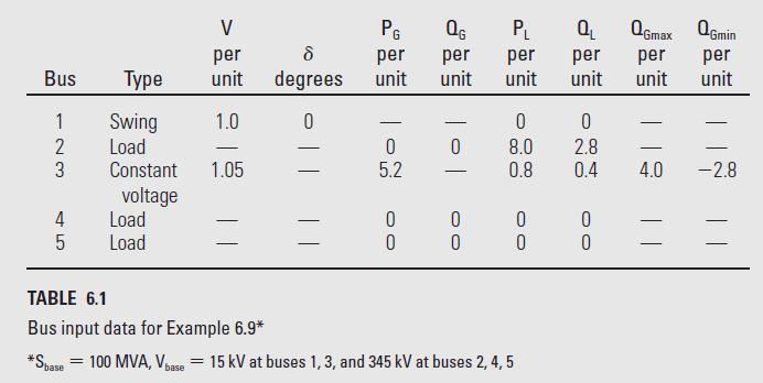
Table 6.2
Bus # 12345 2 3 4 Voltage Magnitude (per unit) 1.000 0.834 1.050 1.019 0.974 Phase Angle PG QG (degrees) (per unit) (per unit) Generation 0.000 -22.407 -0.597 -2.834 -4.548 TOTAL 3.948 0.000 5.200 0.000 0.000 9.148 1.144 0.000 3.376 0.000 0.000 4.516 PL QL (per unit) (per unit) 0.000 8.000 0.800 Load 0.000 0.000 8.800 0.000 2.800 0.400 0.000 0.000 3.200
Step by Step Solution
3.40 Rating (159 Votes )
There are 3 Steps involved in it

Get step-by-step solutions from verified subject matter experts