

Question: Perform a stress analysis for the gear system shown in figure 2. Assume the end supports to act as pins (do not carry any
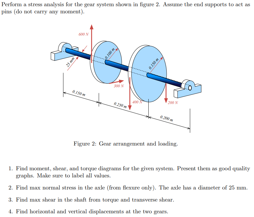
Perform a stress analysis for the gear system shown in figure 2. Assume the end supports to act as pins (do not carry any moment). 25 mm 600 N 0.100 m 300 N 0.150 m 200 N 0.150 m 400 N 0.250 m 0.200 m Figure 2: Gear arrangement and loading. 1. Find moment, shear, and torque diagrams for the given system. Present them as good quality graphs. Make sure to label all values. 2. Find max normal stress in the axle (from flexure only). The axle has a diameter of 25 mm. 3. Find max shear in the shaft from torque and transverse shear. 4. Find horizontal and vertical displacements at the two gears.
Step by Step Solution
There are 3 Steps involved in it

Get step-by-step solutions from verified subject matter experts