

Question: Please Help with these problems In this lab, you will be designing sequential logic circuits using Xilinx ISE tool. This lab worksheet along with your
Please Help with these problems
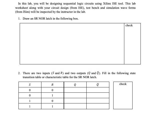
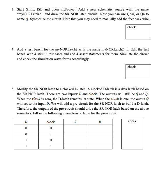
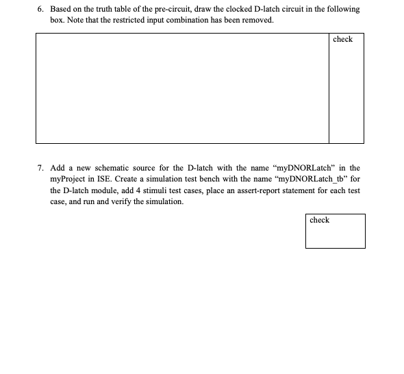
In this lab, you will be designing sequential logic circuits using Xilinx ISE tool. This lab worksheet along with your circuit design (from ISE), test bench and simulation wave forms (from ISim) will be inspected by the instructor in the lab. 1. Draw an SR NOR latch in the following box. check 2. There are two inputs (S and R) and two outputs (Q and Q). Fill in the following state transition table or characteristic table for the SR NOR latch check 0 0 3. Start Xilinx ISE and open myProject. Add a new schematic source with the name "myNORLatch2" and draw the SR NOR latch circuit. Note you can use Qbar, or Qn to name Q. Synthesize the circuit. Note that you may need to manually add the feedback wire check 4. Add a test bench for the myNORLatch2 with the name myNORLatch2 tb. Edit the test bench with 4 stimuli test cases and add 4 assert statements for them. Simulate the circuit and check the simulation wave forms accordingly. check 5. Modify the SR NOR latch to a clocked D-latch. A clocked D-latch is a data latch based on the SR NOR latch. There are two inputs: D and clock. The outputs wll still be Q and Q When the clock is zero, the D-latch remains its state. When the clock is one, the output Q will set to the input D. We will add a pre-circuit for the SR NOR latch to build a D-latch. Therefore, the outputs of the pre-circuit should drive the SR NOR latch based on the above semantics. Fill in the following characteristic table for the pre-circuit check clock 0 0 0 0 6. Based on the truth table of the pre-circuit, draw the clocked D-latch circuit in the following box. Note that the restricted input combination has been removed. check 7. Add a new schematic source for the D-latch with the name "myDNORLatch" in the myProject in ISE. Create a simulation test bench with the name "myDNORLatch tb" for the D-latch module, add 4 stimuli test cases, place an assert-report statement for each test case, and run and verify the simulation. check
Step by Step Solution
There are 3 Steps involved in it

Get step-by-step solutions from verified subject matter experts