

Question: Basic Schematic Design and Simulations In this lab, you will be designing logic circuits using Xilinx ISE tool. Your circuit design (from ISE) and simulation
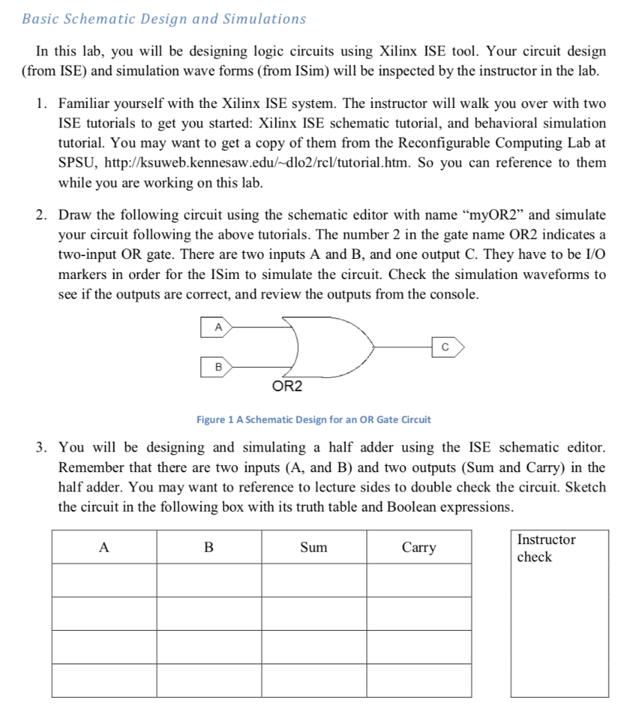
Basic Schematic Design and Simulations In this lab, you will be designing logic circuits using Xilinx ISE tool. Your circuit design (from ISE) and simulation wave forms (from ISim) will be inspected by the instructor in the lab. 1. Familiar yourself with the Xilinx ISE system. The instructor will walk you over with two ISE tutorials to get you started: Xilinx ISE schematic tutorial, and behavioral simulation tutorial. You may want to get a copy of them from the Reconfigurable Computing Lab at SPSU, http://ksuweb.kennesaw.edu/ dlo2/rcl/tutorial.htm. So you can reference to them while you are working on this lab. 2. Draw the following circuit using the schematic editor with name "myOR2" and simulate your circuit following the above tutorials. The number 2 in the gate name OR2 indicates a two-input OR gate. There are two inputs A and B, and one output C. They have to be I/O markers in order for the ISim to simulate the circuit. Check the simulation waveforms to see if the outputs are correct, and review the outputs from the console OR2 Figure 1 A Schematic Design for an OR Gate Circuit 3. You will be designing and simulating a half adder using the ISE schematic editor. Remember that there are two inputs (A, and B) and two outputs (Sum and Carry) in the half adder. You may want to reference to lecture sides to double check the circuit. Sketch the circuit in the following box with its truth table and Boolean expressions. Instructor check Sum Carry Boolean Expressions Instructor check Sketch your circuit here 4. In ISE, add a new schematic source with name "myHalfAdder" and draw the circuit on the schematic editor. Instructor check 5. In ISE, add a new test bench, named myHalfAdder_tb, for the myHalfAdder design. Add 4 test cases as stimuli inputs, and add 4 assert statements to verify the results. Simulate your circuit and check the simulation results. You will be asked to explain each step in the design and simulation process while the instructor is checking your work. Instructor check
Step by Step Solution
There are 3 Steps involved in it

Get step-by-step solutions from verified subject matter experts