

Question: Please Show all steps using Cisco Pakcet Tracer This assignment uses routers, switches, and end devices to create a network that uses variable length subnet
Please Show all steps using Cisco Pakcet Tracer
This assignment uses routers, switches, and end devices to create a network that uses variable
length subnet masks and OSPF routing. Note that the look and feel shown in any screenshots may
be different than the screenshots you see depending on your version of Packet Tracer, operating
systAdd four Cisco routers to the workspace. Go into each of the routers and power them off.
Next, add a HWICT module to the router by dragging it onto an open space in the router photo.
Figure shows an example of Router with a HWICT module added to it Power the routers back
on after adding the module.em and architecture.
Add four Cisco routers to the workspace. Go into each of the routers and power them off.
Next, add a HWICT module to the router by dragging it onto an open space in the router photo.
Figure shows an example of Router with a HWICT module added to it Power the routers back
on after adding the module.
Connect Router to Router using Se on each router.
Connect Router to Router using Se on each router.
Connect Router to Router using Se on each router.
Connect Router to Router using Se on each router.
Add four Cisco switches to the workspace. Use the port GigabitEthernet on each switch to
GigabitEthernet on its respective router.
Add two servers to the workspace. Server should connect to Switch and Server should connect
to Switch using the GigabitEthernet port on each switch.
Add a PC to the workspace near Switch and connect it to FastEthernet on Switch Add a
laptop to the workspace and connect it to Switch FastEthernet
Figure shows the workspace at this point, for reference
IP addresses will be added to each network. Logically, we will get each "LAN" working first and then
work on the serial links between the networks.
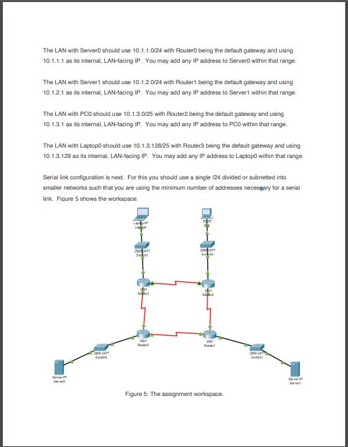
The LAN with Server should use with Router being the default gateway and using
as its internal, LANfacing IP You may add any IP address to Server within that range.
The LAN with Server should use with Router being the default gateway and using
as its internal, LANfacing IP You may add any IP address to Server within that range.
The LAN with PC should use with Router being the default gateway and using
as its internal, LANfacing IP You may add any IP address to PC within that range.
The LAN with Laptop should use with Router being the default gateway and using
as its internal, LANfacing IP You may add any IP address to Laptop within that range.
Serial link configuration is next. For this you should use a single divided or subnetted into
smaller networks such that you are using the minimum number of addresses necessary for a serial
link. Figure shows the workspace.
The next step is to add OSPF routing to each router so that it may discover other networks and
providing routing to them. Youll notice that there are multiple paths that the router may choose to
get to a given network. For example, someone using PC has two paths to get to Server
Add router processes to each router such that each device Server Server PC Laptop can
contact all other devices Server Server PC Laptop on the network. You should use process
ID and area for all OSPF configuration. Do not use static routing to complete this activity.
When done, switch to the Activity Window Figure it may be located on your task bar as a
separate window Click Check Results to receive a grade. Submit a screenshot of the Assessment
Items tab within Activity Results, shown in Figure Be sure to include the Title Bar and Windows
Taskbar, Mac menu bar, or equivalent on Linux not shown in the Figure with your screenshot.The LAN with ServerD should use with Fouter being the default gateway and using as its internal, LANfacing IP You may add any IP address to Server within that range.
The LAN with Servert should use with Routert being the defaul gateway and using as its internal, LANfacing IP You may add any IP address to Servert within that range.
The LAN with PCO should use with Router being the delault gateway and using as its internal, LANfacing IP You may add any IP address to PC within that range.
The LAN with LaptopD should use with Fouter being the default gateway and using as its internal, LANfacing IP You may add any IP address to Laptop within that range.
Serial link contiguration is next. For this you should use a single divided or subnetted into smaller networks such that you are using the minimum number of addresses necessary for a serial link. Fiqure shows the workspace.
Step by Step Solution
There are 3 Steps involved in it
1 Expert Approved Answer
Step: 1 Unlock

Question Has Been Solved by an Expert!
Get step-by-step solutions from verified subject matter experts
Step: 2 Unlock
Step: 3 Unlock