

Question: Problem 1 : Consider the closed - loop control system shown in the figure. 1 . Using MATLAB, 1 . 1 . Derive the open
Problem :
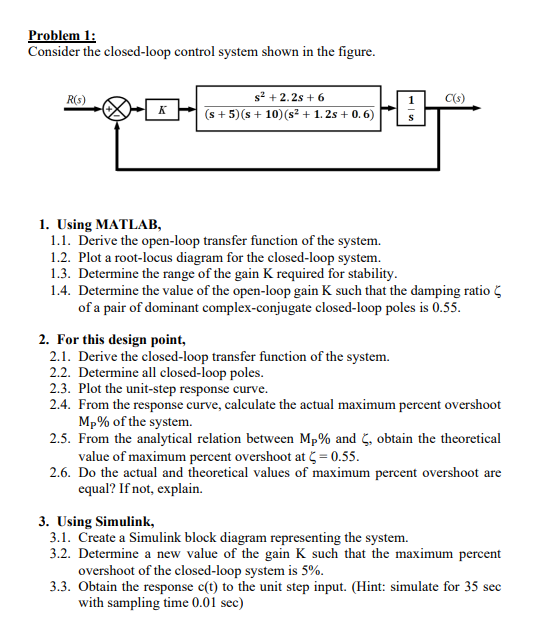
Consider the closedloop control system shown in the figure.
Using MATLAB,
Derive the openloop transfer function of the system.
Plot a rootlocus diagram for the closedloop system.
Determine the range of the gain K required for stability.
Determine the value of the openloop gain K such that the damping ratio zeta of a pair of dominant complexconjugate closedloop poles is
For this design point,
Derive the closedloop transfer function of the system.
Determine all closedloop poles.
Plot the unitstep response curve.
From the response curve, calculate the actual maximum percent overshoot mathrmMmathrmP of the system.
From the analytical relation between mathrmMmathrmP and zeta obtain the theoretical value of maximum percent overshoot at zeta
Do the actual and theoretical values of maximum percent overshoot are equal? If not, explain.
Using Simulink,
Create a Simulink block diagram representing the system.
Determine a new value of the gain K such that the maximum percent overshoot of the closedloop system is
Obtain the response mathrmcmathrmt to the unit step input. Hint: simulate for sec with sampling time sec
Step by Step Solution
There are 3 Steps involved in it
1 Expert Approved Answer
Step: 1 Unlock

Question Has Been Solved by an Expert!
Get step-by-step solutions from verified subject matter experts
Step: 2 Unlock
Step: 3 Unlock