

Question: Problem 1 : For the circuit shown in the below Figure, the input is a voltage source v i ( t ) and the output
Problem :
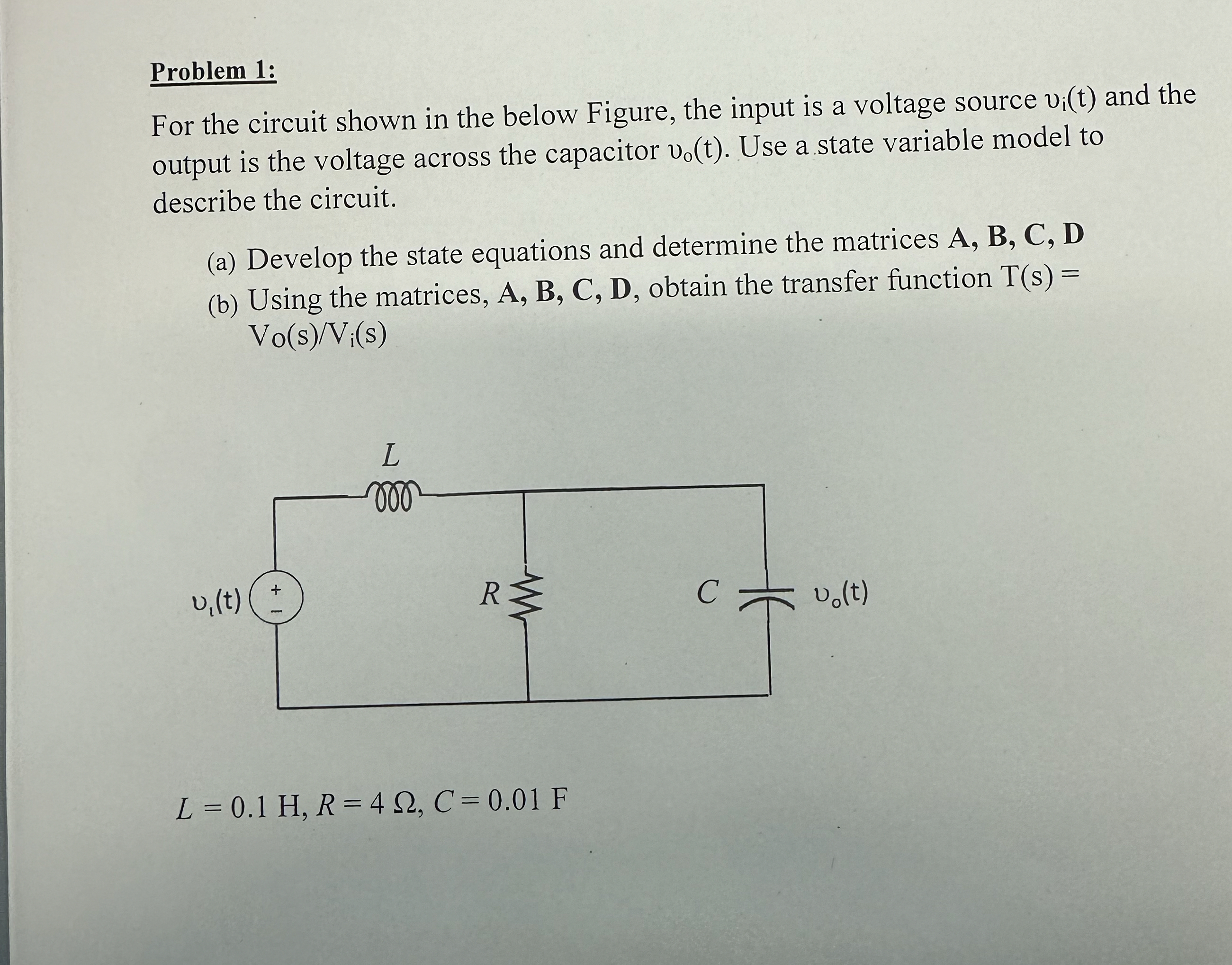
For the circuit shown in the below Figure, the input is a voltage source and the output is the voltage across the capacitor Use a state variable model to describe the circuit.
a Develop the state equations and determine the matrices
b Using the matrices, obtain the transfer function
Step by Step Solution
There are 3 Steps involved in it
1 Expert Approved Answer
Step: 1 Unlock

Question Has Been Solved by an Expert!
Get step-by-step solutions from verified subject matter experts
Step: 2 Unlock
Step: 3 Unlock