

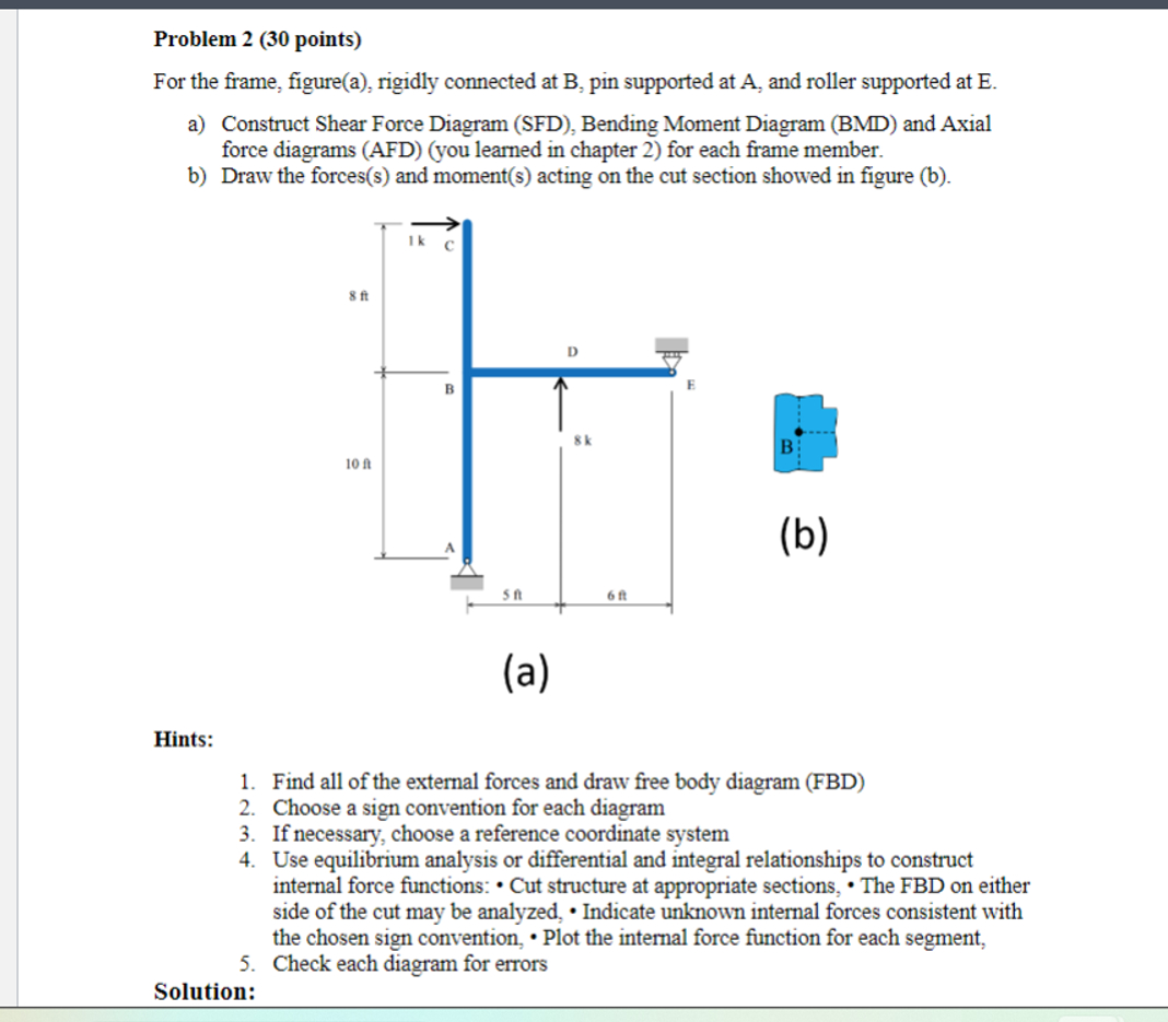
Question: Problem 2 ( 3 0 points ) For the frame, figure ( a ) , rigidly connected at B , pin supported at A ,
Problem points
For the frame, figurea rigidly connected at B pin supported at A and roller supported at E
a Construct Shear Force Diagram SFD Bending Moment Diagram BMD and Axial
force diagrams AFDyou learned in chapter for each frame member.
b Draw the forcess and moments acting on the cut section showed in figure b
Hints:
Find all of the external forces and draw free body diagram FBD
Choose a sign convention for each diagram
If necessary, choose a reference coordinate system
Use equilibrium analysis or differential and integral relationships to construct
internal force functions: Cut structure at appropriate sections, The FBD on either
side of the cut may be analyzed, Indicate unknown internal forces consistent with
the chosen sign convention, Plot the internal force function for each segment,
Check each diagram for errors
Solution:
Step by Step Solution
There are 3 Steps involved in it
1 Expert Approved Answer
Step: 1 Unlock

Question Has Been Solved by an Expert!
Get step-by-step solutions from verified subject matter experts
Step: 2 Unlock
Step: 3 Unlock