

Question: Problem 3: Using Verilog, design the module diagram shown in the next page. The results S2, S1, and S0 will be taken as input codes
Problem 3: Using Verilog, design the module diagram shown in the next page.
The results S2, S1, and S0 will be taken as input codes to the BCD-to-Seven Segment Display modules. The outputs HEX2, HEX1, and HEX0 will drive the seven-segment displays.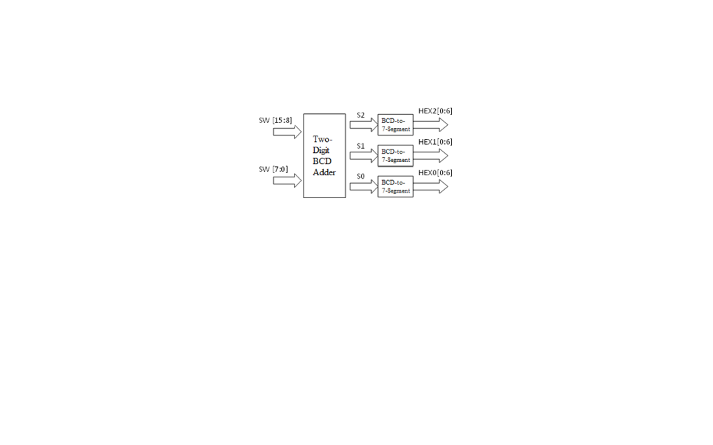
SW 15:8 Two- Digit BCD sw 17:0 Adder $2 S1 HEX200:6] 7-Segment HEX1 0:6 HEX0 0:6 BCD-to- 7-Segment
Step by Step Solution
There are 3 Steps involved in it
1 Expert Approved Answer
Step: 1 Unlock

Question Has Been Solved by an Expert!
Get step-by-step solutions from verified subject matter experts
Step: 2 Unlock
Step: 3 Unlock