

Question: PROCEDURE: A control system with unity negative feedback and P - controller with gain K is shown in Figure 1 . The plant G (
PROCEDURE:
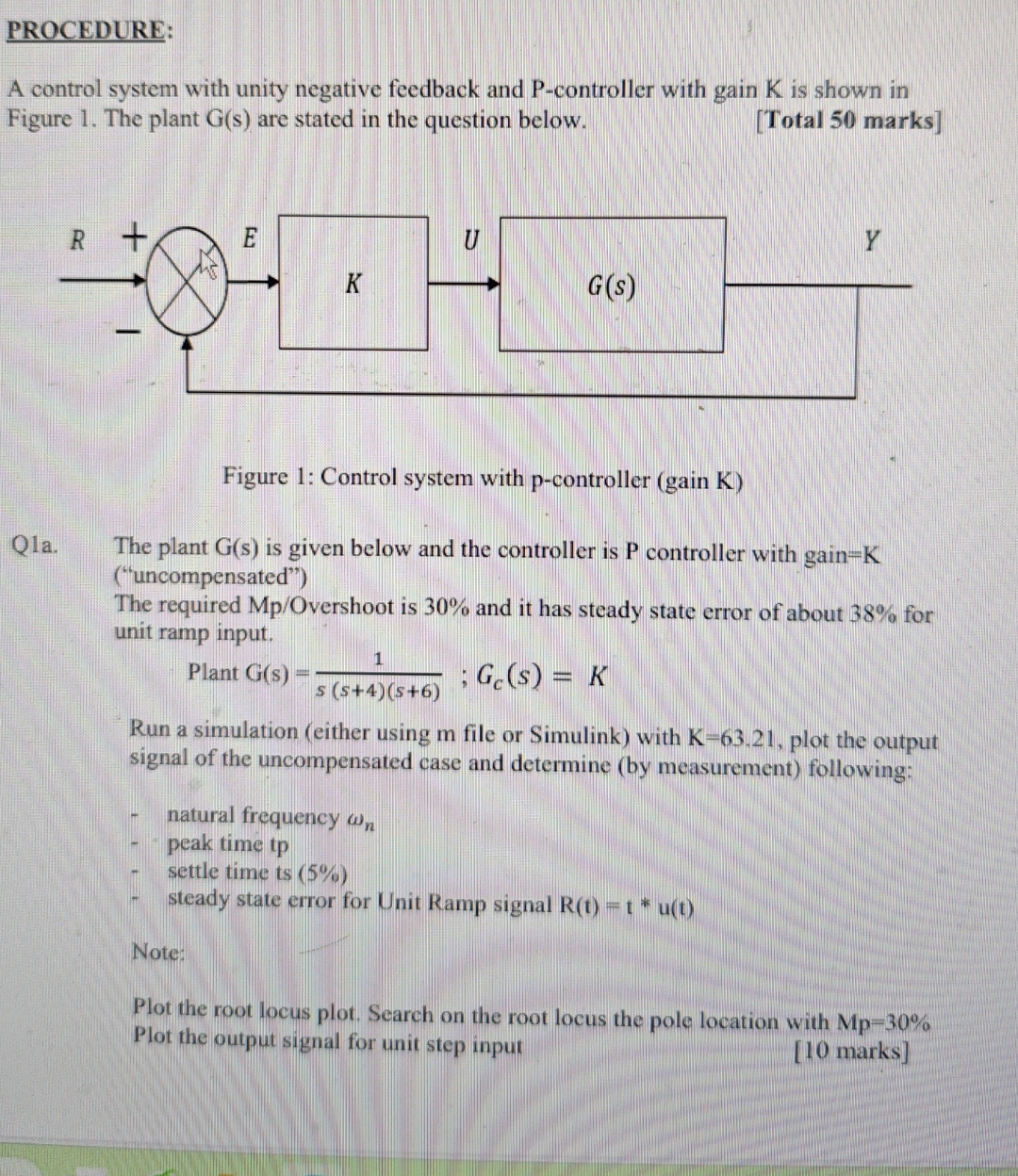
A control system with unity negative feedback and controller with gain is shown in Figure The plant are stated in the question below.
Total marks
Figure : Control system with pcontroller gain K
Qa The plant is given below and the controller is P controller with gainK uncompensated
The required Overshoot is and it has steady state error of about for unit ramp input.
Plant ;
Run a simulation either using file or Simulink with plot the output signal of the uncompensated case and determine by measurement following;
natural frequency
peak time tp
settle time ts
steady state error for Unit Ramp signal
Note:
Plot the root locus plot. Search on the root locus the pole location with Mp Plot the output signal for unit step input marks
Step by Step Solution
There are 3 Steps involved in it
1 Expert Approved Answer
Step: 1 Unlock

Question Has Been Solved by an Expert!
Get step-by-step solutions from verified subject matter experts
Step: 2 Unlock
Step: 3 Unlock