

Question: Q 1 ) For a Drafting Room the ducting system of which is shown below, consider losses at fan inlet and outlet 0 . 1
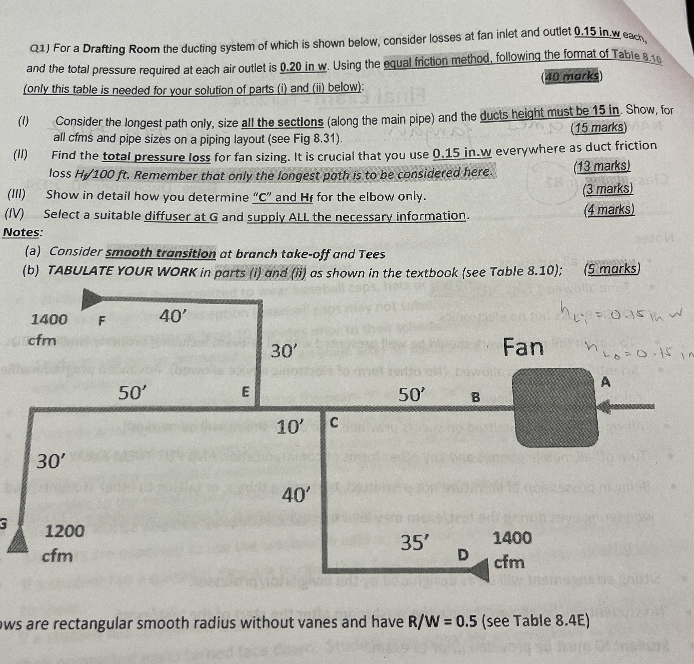
Q For a Drafting Room the ducting system of which is shown below, consider losses at fan inlet and outlet inw each, and the total pressure required at each air outlet is in Using the equal friction method, following the format of Table only this table is needed for your solution of parts i and ii below:
marks
I Consider the longest path only, size all the sections along the main pipe and the ducts height must be in Show, for all cfms and pipe sizes on a piping layout see Fig
marks
II Find the total pressure loss for fan sizing. It is crucial that you use everywhere as duct friction loss Remember that only the longest path is to be considered here.
marks
III Show in detail how you determine C and for the elbow only.
IV Select a suitable diffuser at G and supply ALL the necessary information.
marks
Notes:
marks
a Consider smooth transition at branch takeoff and Tees
b TABULATE YOUR WORK in parts i and ii as shown in the textbook see Table ;
marks
ws are rectangular smooth radius without vanes and have see Table E
Step by Step Solution
There are 3 Steps involved in it
1 Expert Approved Answer
Step: 1 Unlock

Question Has Been Solved by an Expert!
Get step-by-step solutions from verified subject matter experts
Step: 2 Unlock
Step: 3 Unlock