

Question: Question (1): Write the code and flow chart for Task 1 and Task 2 with all details? TASK 1: SMART TRAFFIC LIGHT SYSTEM Observe the
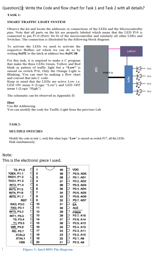
Question (1): Write the code and flow chart for Task 1 and Task 2 with all details? TASK 1: SMART TRAFFIC LIGHT SYSTEM Observe the kit and locate the addresses or connections of the LEDs and the Microcontroller pins. Note that all parts on the kit are properly labeled which mean that the LED PIO is connected to pin P1.0 (Port1 bit o) of the microcontroller and similarly all other LDEs and Switches. The connection is illustrated by the following block diagram: To activate the LEDs we need to activate the respective Buffers set which we can do so by writing OxFE to the latch at address bus OxFC48 LATCH For this task, it is required to make a program that make the three LEDs Green, Yellow and Red blink in pattern of traffic light but a Low" is sensed on switch P16, Only the Orange Light is PORT1 Blinking. You can start by making a flow chart and convert that into C code. Keep in mind that the LEDs are active Low i.e. LED ON mean 0 (Logic "Low") and LED OFF mean 1 (Logic "High") The schematic can be observed in Appendix D. Hint Use Bit Addressing You can modify the code for Traffic Light from the previous Lab 8051 Vec Vec Buffer Voc Vec * TASK 2: MULTIPLE SWITCHES Modify the code in task 1, such that when logic "Low" is sensed on switch P17, all the LEDs blink simultaneously Note: This is the electronic piece I used. T2, P1.0 T2EX, P1.1 RXD1, P12 3 TXD1, P1.3 INT2, P1.4 95 INT3, P1.5 96 INT4, P1.6 07 INT5, P1.7 8 RST 99 RXD, P3.0 10 TXD, P3.1 11 INTO, P32 12 INT1, P3.3 913 TO, P3.4 914 T1, P3.5 15 WR, P3.6 9 16 RD, P3.7 17 XTALZ 18 XTAL1 19 VSS g 20 40 VDD 39 P POO, ADO 38 P PO. 1, AD1 37 PPO 2, AD2 36 P PO 3, AD3 35 P PO.4. AD4 34 P PO 5, AD5 33 P PO 6. AD6 32 P PO.7, ADT 31 PEA 30 PALE 29 P PSEN 28 P P27, A15 27 P P26, A14 26 P P25, A13 25 P P24 A12 24 P P23, A11 23 P P22A10 22 P P21, AS 21 PP20. AS Figure 1: Intel 8051 Pin diagram Question (1): Write the code and flow chart for Task 1 and Task 2 with all details? TASK 1: SMART TRAFFIC LIGHT SYSTEM Observe the kit and locate the addresses or connections of the LEDs and the Microcontroller pins. Note that all parts on the kit are properly labeled which mean that the LED PIO is connected to pin P1.0 (Port1 bit o) of the microcontroller and similarly all other LDEs and Switches. The connection is illustrated by the following block diagram: To activate the LEDs we need to activate the respective Buffers set which we can do so by writing OxFE to the latch at address bus OxFC48 LATCH For this task, it is required to make a program that make the three LEDs Green, Yellow and Red blink in pattern of traffic light but a Low" is sensed on switch P16, Only the Orange Light is PORT1 Blinking. You can start by making a flow chart and convert that into C code. Keep in mind that the LEDs are active Low i.e. LED ON mean 0 (Logic "Low") and LED OFF mean 1 (Logic "High") The schematic can be observed in Appendix D. Hint Use Bit Addressing You can modify the code for Traffic Light from the previous Lab 8051 Vec Vec Buffer Voc Vec * TASK 2: MULTIPLE SWITCHES Modify the code in task 1, such that when logic "Low" is sensed on switch P17, all the LEDs blink simultaneously Note: This is the electronic piece I used. T2, P1.0 T2EX, P1.1 RXD1, P12 3 TXD1, P1.3 INT2, P1.4 95 INT3, P1.5 96 INT4, P1.6 07 INT5, P1.7 8 RST 99 RXD, P3.0 10 TXD, P3.1 11 INTO, P32 12 INT1, P3.3 913 TO, P3.4 914 T1, P3.5 15 WR, P3.6 9 16 RD, P3.7 17 XTALZ 18 XTAL1 19 VSS g 20 40 VDD 39 P POO, ADO 38 P PO. 1, AD1 37 PPO 2, AD2 36 P PO 3, AD3 35 P PO.4. AD4 34 P PO 5, AD5 33 P PO 6. AD6 32 P PO.7, ADT 31 PEA 30 PALE 29 P PSEN 28 P P27, A15 27 P P26, A14 26 P P25, A13 25 P P24 A12 24 P P23, A11 23 P P22A10 22 P P21, AS 21 PP20. AS Figure 1: Intel 8051 Pin diagram
Step by Step Solution
There are 3 Steps involved in it

Get step-by-step solutions from verified subject matter experts