

Question: Question 2. E L4 FD D L3 Fo C FB 1 L B L A 7 The figure (not to scale) shows a one
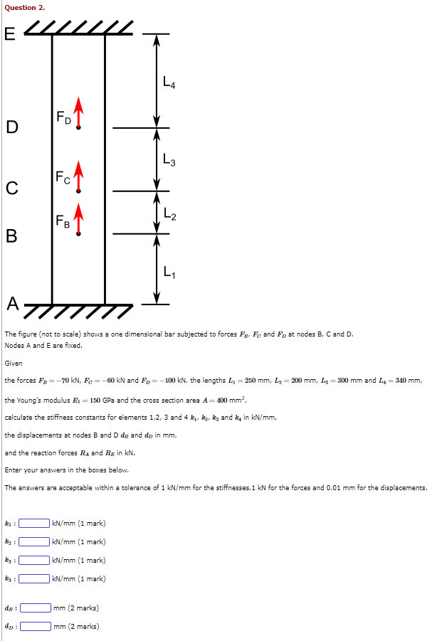
Question 2. E L4 FD D L3 Fo C FB 1 L B L A 7 The figure (not to scale) shows a one dimensional bar subjected to forces FB, Fc and F, at nodes B, C and D. Nodes A and E are fixed. Given the forces FB -70 kN, Fc=-60 kN and Fp=-100 kN, the lengths L = 250 mm, = 200 mm, L-300 mm and L = 340 mm, the Young's modulus E = 150 GPa and the cross section area A = 400 mm, calculate the stiffness constants for elements 1,2, 3 and 4 k, k, kg and k in kN/mm, the displacements at nodes B and D dg and do in mm, and the reaction forces R and Rg in kN. Enter your answers in the boxes below. The answers are acceptable within a tolerance of 1 kN/mm for the stiffnesses, 1 kN for the forces and 0.01 mm for the displacements. kN/mm (1 mark) kN/mm (1 mark) ky: kN/mm (1 mark) ky: kN/mm (1 mark) dB: mm (2 marks) dp: mm (2 marks)
Step by Step Solution
There are 3 Steps involved in it

Get step-by-step solutions from verified subject matter experts