 Question 3: Revise the handling methods and identify the new transfer batch sizes for each handling step. Where possible, reduce the number of storage locations at workstations. Summarize the results by updating Table 1.
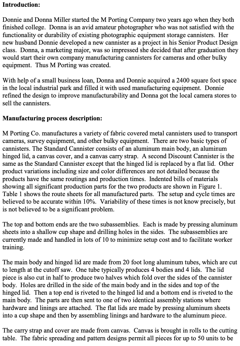
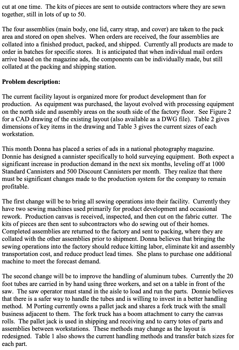
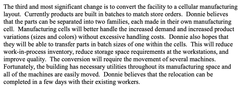
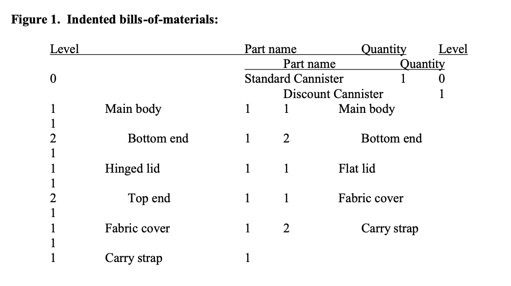
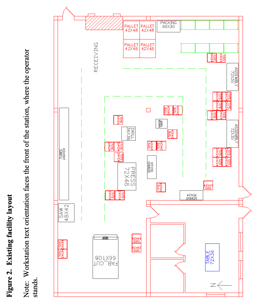
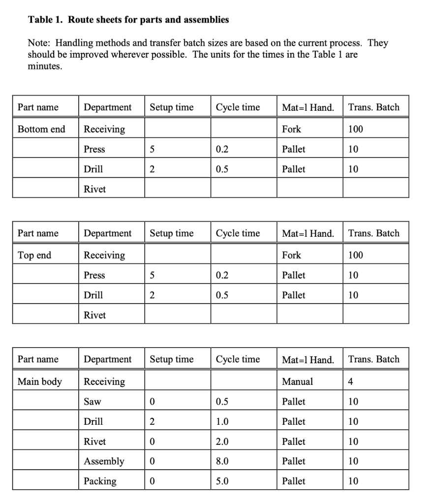
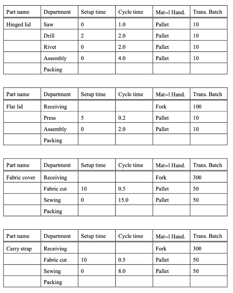
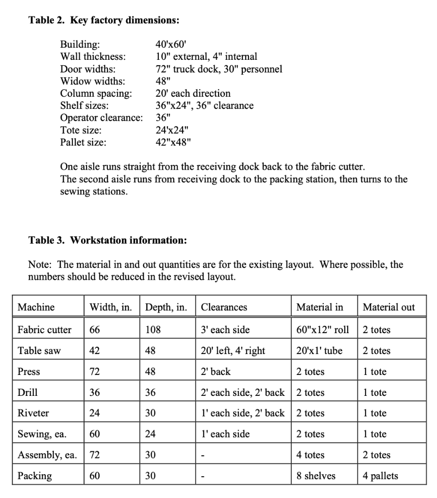
Introduction: Donnie and Donna Miller started the M Porting Company two years ago when they both finished college. Donna is an avid amateur photographer who was not satisfied with the functionality or durability of existing photographic equipment storage cannisters. Her new husband Donnie developed a new cannister as a project in his Senior Product Design class. Donna, a marketing major, was so impressed she decided that after graduation they would start their own company manufacturing cannisters for cameras and other bulky equipment. Thus M Porting was created. With help of a small business loan, Donna and Donnie acquired a 2400 square foot space in the local industrial park and filled it with used manufacturing equipment. Donnie refined the design to improve manufacturability and Donna got the local camera stores to sell the cannisters. Manufacturing process description: M Porting Co. manufactures a variety of fabric covered metal cannisters used to transport cameras, survey equipment, and other bulky equipment. There are two basic types of cannisters. The Standard Cannister consists of an aluminum main body, an aluminum hinged lid, a canvas cover, and a canvas carry strap. A second Discount Cannister is the same as the Standard Cannister except that the hinged lid is replaced by a flat lid. Other product variations including size and color differences are not detailed because the products have the same routings and production times. Indented bills of materials showing all significant production parts for the two products are shown in Figure 1. Table 1 shows the route sheets for all manufactured parts. The setup and cycle times are believed to be accurate within 10%. Variability of these times is not know precisely, but is not believed to be a significant problem. The top and bottom ends are the two subassemblies. Each is made by pressing aluminum sheets into a shallow cup shape and drilling holes in the sides. The subassemblies are currently made and handled in lots of 10 to minimize setup cost and to facilitate worker training. The main body and hinged lid are made from 20 foot long aluminum tubes, which are cut to length at the cutoff saw. One tube typically produces 4 bodies and 4 lids. The lid piece is also cut in half to produce two halves which fold over the sides of the cannister body. Holes are drilled in the side of the main body and in the sides and top of the hinged lid. Then a top end is riveted to the hinged lid and a bottom end is riveted to the main body. The parts are then sent to one of two identical assembly stations where hardware and linings are attached. The flat lids are made by pressing aluminum sheets into a cup shape and then by assembling linings and hardware to the aluminum piece. The carry strap and cover are made from canvas. Canvas is brought in rolls to the cutting table. The fabric spreading and pattern designs permit all pieces for up to 50 units to be cut at one time. The kits of pieces are sent to outside contractors where they are sewn together, still in lots of up to 50 . The four assemblies (main body, one lid, carry strap, and cover) are taken to the pack area and stored on open shelves. When orders are received, the four assemblies are collated into a finished product, packed, and shipped. Currently all products are made to order in batches for specific stores. It is anticipated that when individual mail orders arrive based on the magazine ads, the components can be individually made, but still collated at the packing and shipping station. Problem description: The current facility layout is organized more for product development than for production. As equipment was purchased, the layout evolved with processing equipment on the north side and assembly areas on the south side of the factory floor. See Figure 2 for a CAD drawing of the existing layout (also available as a DWG file). Table 2 gives dimensions of key items in the drawing and Table 3 gives the current sizes of each workstation. This month Donna has placed a series of ads in a national photography magazine. Donnie has designed a cannister specifically to hold surveying equipment. Both expect a significant increase in production demand in the next six months, leveling off at 1000 Standard Cannisters and 500 Discount Cannisters per month. They realize that there must be significant changes made to the production system for the company to remain profitable. The first change will be to bring all sewing operations into their facility. Currently they have two sewing machines used primarily for product development and occasional rework. Production canvas is received, inspected, and then cut on the fabric cutter. The kits of pieces are then sent to subcontractors who do sewing out of their homes. Completed assemblies are returned to the factory and sent to packing, where they are collated with the other assemblies prior to shipment. Donna believes that bringing the sewing operations into the factory should reduce kitting labor, eliminate kit and assembly transportation cost, and reduce product lead times. She plans to purchase one additional machine to meet the forecast demand. The second change will be to improve the handling of aluminum tubes. Currently the 20 foot tubes are carried in by hand using three workers, and set on a table in front of the saw. The saw operator must stand in the aisle to load and run the parts. Donnie believes that there is a safer way to handle the tubes and is willing to invest in a better handling method. M Porting currently owns a pallet jack and shares a fork truck with the small business adjacent to them. The fork truck has a boom attachment to carry the canvas rolls. The pallet jack is used in shipping and receiving and to carry totes of parts and assemblies between workstations. These methods may change as the layout is redesigned. Table 1 also shows the current handling methods and transfer batch sizes for each part. The third and most significant change is to convert the facility to a cellular manufacturing layout. Currently products are built in batches to match store orders. Donnie believes that the parts can be separated into two families, each made in their own manufacturing cell. Manufacturing cells will better handle the increased demand and increased product variations (sizes and colors) without excessive handling costs. Donnie also hopes that they will be able to transfer parts in batch sizes of one within the cells. This will reduce work-in-process inventory, reduce storage space requirements at the workstations, and improve quality. The conversion will require the movement of several machines. Fortunately, the building has necessary utilities throughout its manufacturing space and all of the machines are easily moved. Donnie believes that the relocation can be completed in a few days with their existing workers. Figure 1. Indented bills-of-materials: Figure 2. Existing facility layout Note: Workstation text orientation faces the front of the station, where the operator stands. Table 1. Route sheets for parts and assemblies Note: Handling methods and transfer batch sizes are based on the current process. They should be improved wherever possible. The units for the times in the Table 1 are minutes. \begin{tabular}{|l|l|l|l|l|l|} \hline Part name & Department & Setup time & Cycle time & Mat=1 Hand. & Trans. Batch \\ \hline \hline Hinged lid & Saw & 0 & 1.0 & Pallet & 10 \\ \hline & Drill & 2 & 2.0 & Pallet & 10 \\ \hline & Rivet & 0 & 2.0 & Pallet & 10 \\ \hline & Assembly & 0 & 4.0 & Pallet & 10 \\ \hline & Packing & & & & \\ \hline \end{tabular} \begin{tabular}{|l|l|l|l|l|l|} \hline Part name & Department & Setup time & Cycle time & Mat=1 Hand. & Trans. Batch \\ \hline \hline Flat lid & Receiving & & & Fork & 100 \\ \hline & Press & 5 & 0.2 & Pallet & 10 \\ \hline & Assembly & 0 & 2.0 & Pallet & 10 \\ \hline & Packing & & & & \\ \hline \end{tabular} \begin{tabular}{|l|l|l|l|l|l|} \hline Part name & Department & Setup time & Cycle time & Mat=1 Hand. & Trans. Batch \\ \hline \hline Fabric cover & Receiving & & & Fork & 300 \\ \hline & Fabric cut & 10 & 0.5 & Pallet & 50 \\ \hline & Sewing & 0 & 15.0 & Pallet & 50 \\ \hline & Packing & & & & \\ \hline \end{tabular} \begin{tabular}{|l|l|l|l|l|l|} \hline Part name & Department & Setup time & Cycle time & Mat=1 Hand. & Trans. Batch \\ \hline \hline Carry strap & Receiving & & & Fork & 300 \\ \hline & Fabric cut & 10 & 0.5 & Pallet & 50 \\ \hline & Sewing & 0 & 8.0 & Pallet & 50 \\ \hline & Packing & & & & \\ \hline \end{tabular} Table 2. Key factory dimensions: One aisle runs straight from the receiving dock back to the fabric cutter. The second aisle runs from receiving dock to the packing station, then turns to the sewing stations. Table 3. Workstation information: Note: The material in and out quantities are for the existing layout. Where possible, the numbers should be reduced in the revised layout. Introduction: Donnie and Donna Miller started the M Porting Company two years ago when they both finished college. Donna is an avid amateur photographer who was not satisfied with the functionality or durability of existing photographic equipment storage cannisters. Her new husband Donnie developed a new cannister as a project in his Senior Product Design class. Donna, a marketing major, was so impressed she decided that after graduation they would start their own company manufacturing cannisters for cameras and other bulky equipment. Thus M Porting was created. With help of a small business loan, Donna and Donnie acquired a 2400 square foot space in the local industrial park and filled it with used manufacturing equipment. Donnie refined the design to improve manufacturability and Donna got the local camera stores to sell the cannisters. Manufacturing process description: M Porting Co. manufactures a variety of fabric covered metal cannisters used to transport cameras, survey equipment, and other bulky equipment. There are two basic types of cannisters. The Standard Cannister consists of an aluminum main body, an aluminum hinged lid, a canvas cover, and a canvas carry strap. A second Discount Cannister is the same as the Standard Cannister except that the hinged lid is replaced by a flat lid. Other product variations including size and color differences are not detailed because the products have the same routings and production times. Indented bills of materials showing all significant production parts for the two products are shown in Figure 1. Table 1 shows the route sheets for all manufactured parts. The setup and cycle times are believed to be accurate within 10%. Variability of these times is not know precisely, but is not believed to be a significant problem. The top and bottom ends are the two subassemblies. Each is made by pressing aluminum sheets into a shallow cup shape and drilling holes in the sides. The subassemblies are currently made and handled in lots of 10 to minimize setup cost and to facilitate worker training. The main body and hinged lid are made from 20 foot long aluminum tubes, which are cut to length at the cutoff saw. One tube typically produces 4 bodies and 4 lids. The lid piece is also cut in half to produce two halves which fold over the sides of the cannister body. Holes are drilled in the side of the main body and in the sides and top of the hinged lid. Then a top end is riveted to the hinged lid and a bottom end is riveted to the main body. The parts are then sent to one of two identical assembly stations where hardware and linings are attached. The flat lids are made by pressing aluminum sheets into a cup shape and then by assembling linings and hardware to the aluminum piece. The carry strap and cover are made from canvas. Canvas is brought in rolls to the cutting table. The fabric spreading and pattern designs permit all pieces for up to 50 units to be cut at one time. The kits of pieces are sent to outside contractors where they are sewn together, still in lots of up to 50 . The four assemblies (main body, one lid, carry strap, and cover) are taken to the pack area and stored on open shelves. When orders are received, the four assemblies are collated into a finished product, packed, and shipped. Currently all products are made to order in batches for specific stores. It is anticipated that when individual mail orders arrive based on the magazine ads, the components can be individually made, but still collated at the packing and shipping station. Problem description: The current facility layout is organized more for product development than for production. As equipment was purchased, the layout evolved with processing equipment on the north side and assembly areas on the south side of the factory floor. See Figure 2 for a CAD drawing of the existing layout (also available as a DWG file). Table 2 gives dimensions of key items in the drawing and Table 3 gives the current sizes of each workstation. This month Donna has placed a series of ads in a national photography magazine. Donnie has designed a cannister specifically to hold surveying equipment. Both expect a significant increase in production demand in the next six months, leveling off at 1000 Standard Cannisters and 500 Discount Cannisters per month. They realize that there must be significant changes made to the production system for the company to remain profitable. The first change will be to bring all sewing operations into their facility. Currently they have two sewing machines used primarily for product development and occasional rework. Production canvas is received, inspected, and then cut on the fabric cutter. The kits of pieces are then sent to subcontractors who do sewing out of their homes. Completed assemblies are returned to the factory and sent to packing, where they are collated with the other assemblies prior to shipment. Donna believes that bringing the sewing operations into the factory should reduce kitting labor, eliminate kit and assembly transportation cost, and reduce product lead times. She plans to purchase one additional machine to meet the forecast demand. The second change will be to improve the handling of aluminum tubes. Currently the 20 foot tubes are carried in by hand using three workers, and set on a table in front of the saw. The saw operator must stand in the aisle to load and run the parts. Donnie believes that there is a safer way to handle the tubes and is willing to invest in a better handling method. M Porting currently owns a pallet jack and shares a fork truck with the small business adjacent to them. The fork truck has a boom attachment to carry the canvas rolls. The pallet jack is used in shipping and receiving and to carry totes of parts and assemblies between workstations. These methods may change as the layout is redesigned. Table 1 also shows the current handling methods and transfer batch sizes for each part. The third and most significant change is to convert the facility to a cellular manufacturing layout. Currently products are built in batches to match store orders. Donnie believes that the parts can be separated into two families, each made in their own manufacturing cell. Manufacturing cells will better handle the increased demand and increased product variations (sizes and colors) without excessive handling costs. Donnie also hopes that they will be able to transfer parts in batch sizes of one within the cells. This will reduce work-in-process inventory, reduce storage space requirements at the workstations, and improve quality. The conversion will require the movement of several machines. Fortunately, the building has necessary utilities throughout its manufacturing space and all of the machines are easily moved. Donnie believes that the relocation can be completed in a few days with their existing workers. Figure 1. Indented bills-of-materials: Figure 2. Existing facility layout Note: Workstation text orientation faces the front of the station, where the operator stands. Table 1. Route sheets for parts and assemblies Note: Handling methods and transfer batch sizes are based on the current process. They should be improved wherever possible. The units for the times in the Table 1 are minutes. \begin{tabular}{|l|l|l|l|l|l|} \hline Part name & Department & Setup time & Cycle time & Mat=1 Hand. & Trans. Batch \\ \hline \hline Hinged lid & Saw & 0 & 1.0 & Pallet & 10 \\ \hline & Drill & 2 & 2.0 & Pallet & 10 \\ \hline & Rivet & 0 & 2.0 & Pallet & 10 \\ \hline & Assembly & 0 & 4.0 & Pallet & 10 \\ \hline & Packing & & & & \\ \hline \end{tabular} \begin{tabular}{|l|l|l|l|l|l|} \hline Part name & Department & Setup time & Cycle time & Mat=1 Hand. & Trans. Batch \\ \hline \hline Flat lid & Receiving & & & Fork & 100 \\ \hline & Press & 5 & 0.2 & Pallet & 10 \\ \hline & Assembly & 0 & 2.0 & Pallet & 10 \\ \hline & Packing & & & & \\ \hline \end{tabular} \begin{tabular}{|l|l|l|l|l|l|} \hline Part name & Department & Setup time & Cycle time & Mat=1 Hand. & Trans. Batch \\ \hline \hline Fabric cover & Receiving & & & Fork & 300 \\ \hline & Fabric cut & 10 & 0.5 & Pallet & 50 \\ \hline & Sewing & 0 & 15.0 & Pallet & 50 \\ \hline & Packing & & & & \\ \hline \end{tabular} \begin{tabular}{|l|l|l|l|l|l|} \hline Part name & Department & Setup time & Cycle time & Mat=1 Hand. & Trans. Batch \\ \hline \hline Carry strap & Receiving & & & Fork & 300 \\ \hline & Fabric cut & 10 & 0.5 & Pallet & 50 \\ \hline & Sewing & 0 & 8.0 & Pallet & 50 \\ \hline & Packing & & & & \\ \hline \end{tabular} Table 2. Key factory dimensions: One aisle runs straight from the receiving dock back to the fabric cutter. The second aisle runs from receiving dock to the packing station, then turns to the sewing stations. Table 3. Workstation information: Note: The material in and out quantities are for the existing layout. Where possible, the numbers should be reduced in the revised layout


