

Question: QUESTION 5 (a) Three flip-flops are connected and subjected to clock and input signals shown in Figure 5 (i). Complete the timing diagram for
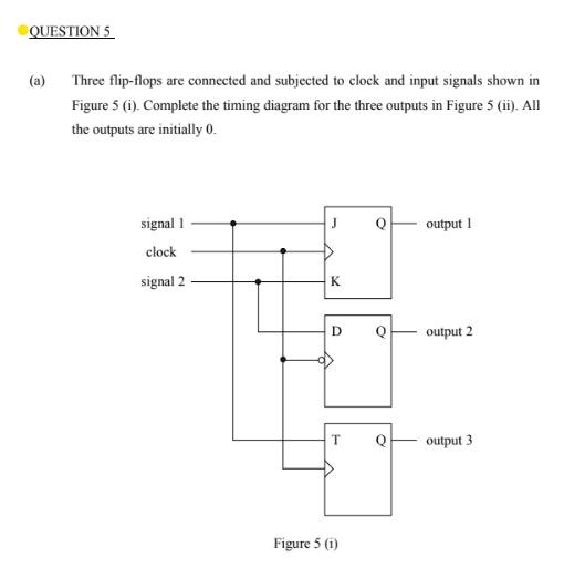
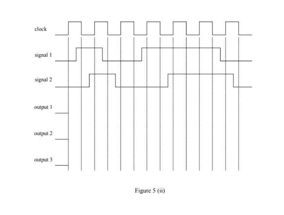
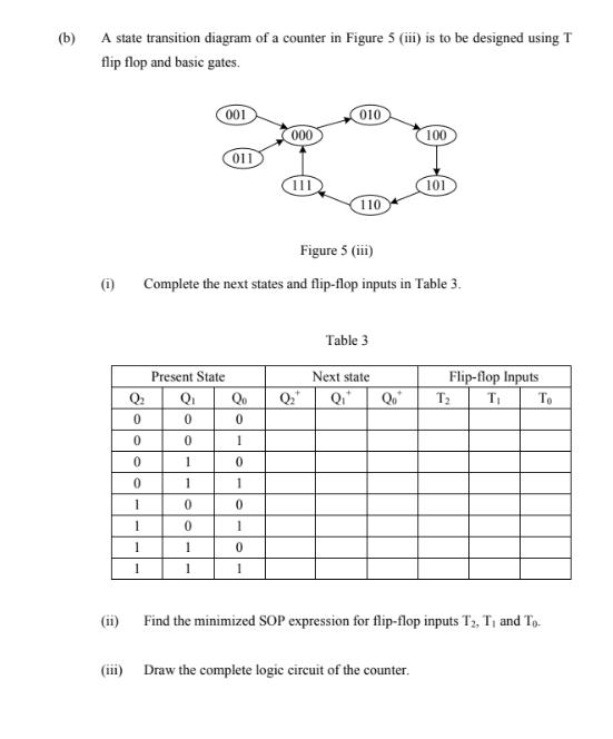
QUESTION 5 (a) Three flip-flops are connected and subjected to clock and input signals shown in Figure 5 (i). Complete the timing diagram for the three outputs in Figure 5 (ii). All the outputs are initially 0. signal 1 J Q output 1 clock signal 2 K D output 2 output 3 Figure 5 (i) clock signal 1 signal 2 output I output 2 output 3 Figure 5 (ii) (b) A state transition diagram of a counter in Figure 5 (iii) is to be designed using T flip flop and basic gates. 001 010 000 100 011 101 110 Figure 5 (iii) (1) Complete the next states and flip-flop inputs in Table 3. Table 3 Present State Next state Flip-flop Inputs Q. Qi Qo Q Qo T2 To 1 1 1 (ii) Find the minimized SOP expression for flip-flop inputs T2, T, and To. (iii) Draw the complete logic circuit of the counter.
Step by Step Solution
3.50 Rating (157 Votes )
There are 3 Steps involved in it

Get step-by-step solutions from verified subject matter experts