

Question: Schematic below represents a given circuit with two inputs A and B 2-bits each and 2 outputs Sum_reg and Carry_reg 2-bits each as wee.
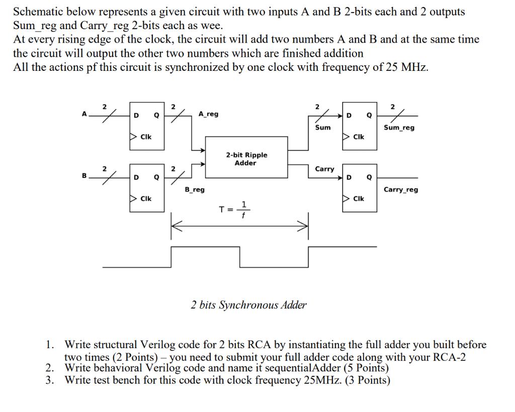
Schematic below represents a given circuit with two inputs A and B 2-bits each and 2 outputs Sum_reg and Carry_reg 2-bits each as wee. At every rising edge of the clock, the circuit will add two numbers A and B and at the same time the circuit will output the other two numbers which are finished addition All the actions pf this circuit is synchronized by one clock with frequency of 25 MHz. 2 A D Q A_reg Clk 2 2 D Q Sum Sum_reg Clk 2-bit Ripple Adder Carry D Q Carry_reg Clk B 3 2 D Q B_reg Clk === 2 bits Synchronous Adder 1. Write structural Verilog code for 2 bits RCA by instantiating the full adder you built before two times (2 Points) - you need to submit your full adder code along with your RCA-2 2. Write behavioral Verilog code and name it sequential Adder (5 Points) 3. Write test bench for this code with clock frequency 25MHz. (3 Points)
Step by Step Solution
There are 3 Steps involved in it

Get step-by-step solutions from verified subject matter experts