

Question: Simulate a small virtual memory system with TLB and L1 D-cache with following assumptions: The memory is byte addressable Memory accesses are to 1-byte words
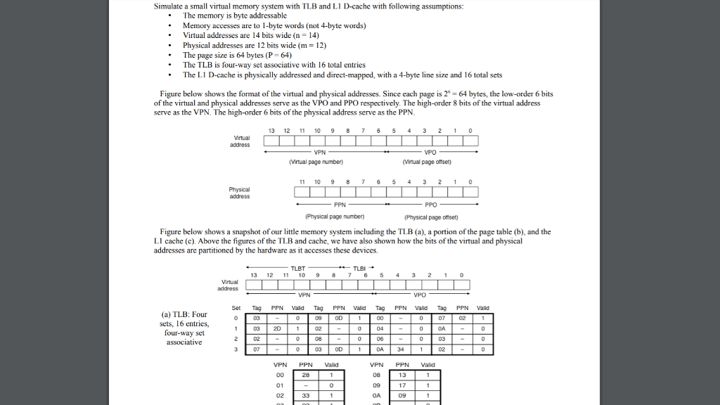
Simulate a small virtual memory system with TLB and L1 D-cache with following assumptions:
The memory is byte addressable Memory accesses are to 1-byte words (not 4-byte words)
Virtual addresses are 14 bits wide (n = 14)
Physical addresses are 12 bits wide (m = 12) The page size is 64 bytes (P = 64)
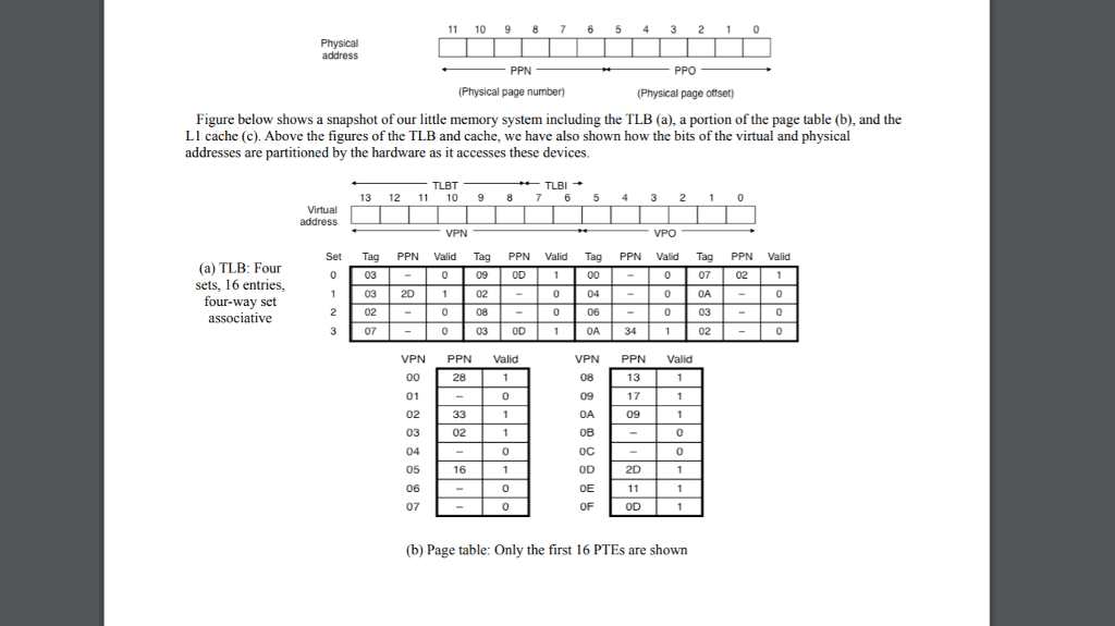
The TLB is four-way set associative with 16 total entries
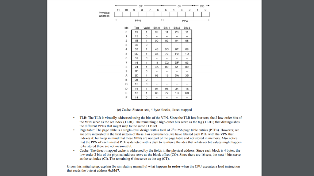
The L1 D-cache is physically addressed and direct-mapped, with a 4-byte line size and 16 total sets
Given this initial setup, explain (by simulating manually) what happens in order when the CPU executes a load instruction that reads the byte at address 0x03d7.
Simulate a small virtual memory system with TLB and LI D-cache with following assumptions: The memory is byte addressable Memory accesses are to 1-byte words (not 4-byte words) Virtual addresses are 14 bits wide (n 14) Physical addresses are 12 bits wide (m-12) The page size is 64 bytes (P 64) . .The TLB is four-way set associative with 16 total entries The L1 D-cache is physically addressed and direct-mapped, with a 4-byte line size and 16 total sets Figure below shows the format of the virtual and physical addresses. Since each page is 2 64 bytes, the low-order 6 bits of the virtual and physical addresses serve as the VPO and PPO respectively. The high-order 8 bits of the virtual address serve as the VPN. The high-order 6 bits of the physical address serve as the PPN 13 12 10 987 6 5 43 2 (Virtual page number Virtual page offser 11 10 9 8 76 53 2 0 PPN Physical page numberj Physical page oftset) Figure below shows a snapshot of our little memory system including the TLB (a), a portion of the page table (b), and the LI cache (c). Above the figures of the TLB and cache, we have also shown how the bits of the virtual and physical addresses are partitioned by the hardware as it accesses these devices. TLBTTLBI 13 12 11 10 976 5 43 2 Set Tag PPN Vaid Tag PPN Valid Tag PPN Valid Tag PPN Valid (a) TLB: Four sets, 16 entries, four-way set associative 09 OD 07 03 2D 1 0 OA 08 06 03 OD 0A VPN PPN Vali PPN Valid VPN 08 09 OA 17 01 02 Simulate a small virtual memory system with TLB and LI D-cache with following assumptions: The memory is byte addressable Memory accesses are to 1-byte words (not 4-byte words) Virtual addresses are 14 bits wide (n 14) Physical addresses are 12 bits wide (m-12) The page size is 64 bytes (P 64) . .The TLB is four-way set associative with 16 total entries The L1 D-cache is physically addressed and direct-mapped, with a 4-byte line size and 16 total sets Figure below shows the format of the virtual and physical addresses. Since each page is 2 64 bytes, the low-order 6 bits of the virtual and physical addresses serve as the VPO and PPO respectively. The high-order 8 bits of the virtual address serve as the VPN. The high-order 6 bits of the physical address serve as the PPN 13 12 10 987 6 5 43 2 (Virtual page number Virtual page offser 11 10 9 8 76 53 2 0 PPN Physical page numberj Physical page oftset) Figure below shows a snapshot of our little memory system including the TLB (a), a portion of the page table (b), and the LI cache (c). Above the figures of the TLB and cache, we have also shown how the bits of the virtual and physical addresses are partitioned by the hardware as it accesses these devices. TLBTTLBI 13 12 11 10 976 5 43 2 Set Tag PPN Vaid Tag PPN Valid Tag PPN Valid Tag PPN Valid (a) TLB: Four sets, 16 entries, four-way set associative 09 OD 07 03 2D 1 0 OA 08 06 03 OD 0A VPN PPN Vali PPN Valid VPN 08 09 OA 17 01 02
Step by Step Solution
There are 3 Steps involved in it
To simulate the operation of the virtual memory system including the TLB and L1 Dcache when the CPU executes a load instruction reading from the byte at address 0x03d7 we need to break the process dow... View full answer

Get step-by-step solutions from verified subject matter experts