

Question: Simulation and Analysis of a Vehicle Suspension System Using MATLAB & SIMULINK MENG 324-Vibrations & System Dynamics Project-30% (Report and Presentation) Timeline: 16/04/2018 The main
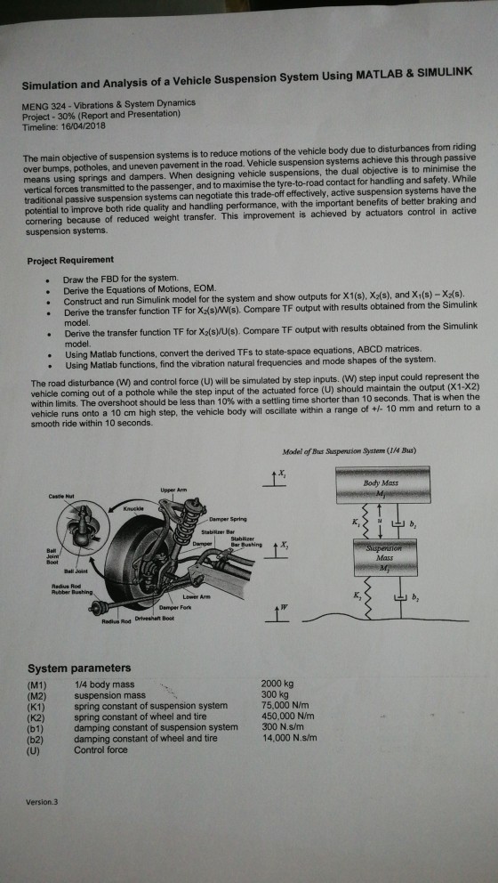
Simulation and Analysis of a Vehicle Suspension System Using MATLAB & SIMULINK MENG 324-Vibrations & System Dynamics Project-30% (Report and Presentation) Timeline: 16/04/2018 The main objective of suspension systems is to reduce motions of the vehicle body due to disturbances from riding uspension systems achieve this through passive over bumps, potholes, and uneven pavement in the road. Vehicle s means using springs and dampers. When designing vehicle suspensions, the dual objective is to minimise the nd to maximise the tyre-to-road contact for handling and safety. While vertical forces transmitted to the passenger, a traditional passive suspension systems can negotiate this trade-off effectively, active suspension systems have the cornering because of reduced weight transfer. This improvement is achieved by actuators control in active suspension systems. Project Requirement Draw the FBD for the system. Construct and run Simulink model for the system and show outputs for X1(s), X2(s), and X(s)-Xds). Derive the Equations of Motions, EOM. .Derive the transfer function TF for X(s)W(s). Compare TF output with results obtained from the Sim . Derive the transfer function TF for Xa(syU(s) Compare TF output with results obtained from the Simuli ulink model model. Using Matiab functions, convert the der rived TFs to state-space equations, ABCD matrices. Using Matiab functions, find the vibration natural frequencies and mode shapes of the system. The road disturbance (W) and control force (U) will be simulated by step inputs. (W) step input could represent the vehicle coming out of a pothole while the step input of the actuated force (U) should maintain the output (X1-X2) within limits. The overshoot should be less than 10% with a settling time shorter than 10 seconds. That is when the vehicle runs onto a 10 cm high step, the vehicle body will oscillate within a range of +1 10 mm smooth ride within 10 seconds. and return to a Model of Bus Sauspension System (1/4 Bus) Body Mass Upper Ann Damper Spring Bar Bushing Mass Ball Joint Radius Rod Lower Are K, b, Damper Fork Radius Rod Drtveshat Bost System parameters (M1) 1/4 body mass (M2) suspension mass (K1) spring constant of suspension system (K2) (b1) (b2) (U) Control force 2000 kg 75,000 N/mm 450,000 N/m spring constant of wheel and tire damping constant of suspension system damping constant of wheel and tire 300 N.s/m 14,000 N.s/m Version.3
Step by Step Solution
There are 3 Steps involved in it

Get step-by-step solutions from verified subject matter experts