

Question: Solve using Multisim Experiment 7.7 Consider the resistive circuit depicted in Figure 7.22. (a) Launch Multisim and capture the circuit under consideration. (b) Temporarily deactivate
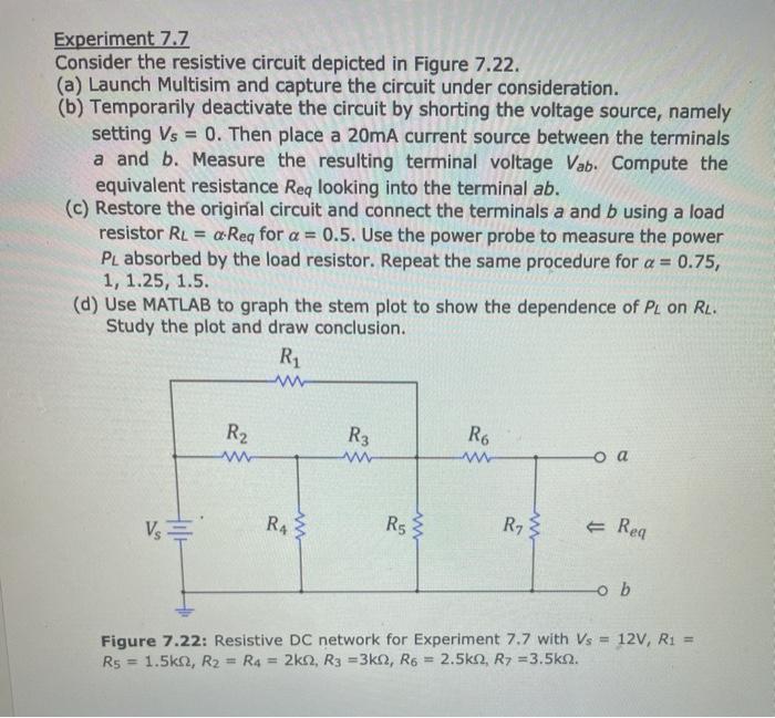
Experiment 7.7 Consider the resistive circuit depicted in Figure 7.22. (a) Launch Multisim and capture the circuit under consideration. (b) Temporarily deactivate the circuit by shorting the voltage source, namely setting Vs = 0. Then place a 20mA current source between the terminals a and b. Measure the resulting terminal voltage Vab. Compute the equivalent resistance Req looking into the terminal ab. (c) Restore the original circuit and connect the terminals a and b using a load resistor RL = a Reg for a = 0.5. Use the power probe to measure the power PL absorbed by the load resistor. Repeat the same procedure for a = 0.75, 1, 1.25, 1.5. (d) Use MATLAB to graph the stem plot to show the dependence of Peon RL. Study the plot and draw conclusion. R1 w R R3 R6 w -o a Vs R43 R RS } Ry & Rea -ob Figure 7.22: Resistive DC network for Experiment 7.7 with Vs = 12V, R1 = Rs = 1.5ks, R2 = R4 = 2k2, R3 =3k2, R6 = 2.5k 2, R7 = 3.5k92
Step by Step Solution
There are 3 Steps involved in it

Get step-by-step solutions from verified subject matter experts