

Question: For the Shift Register shown below: a. (3 Pts) Construct the State Transition Diagram (X is the Input and Z is the output. Q
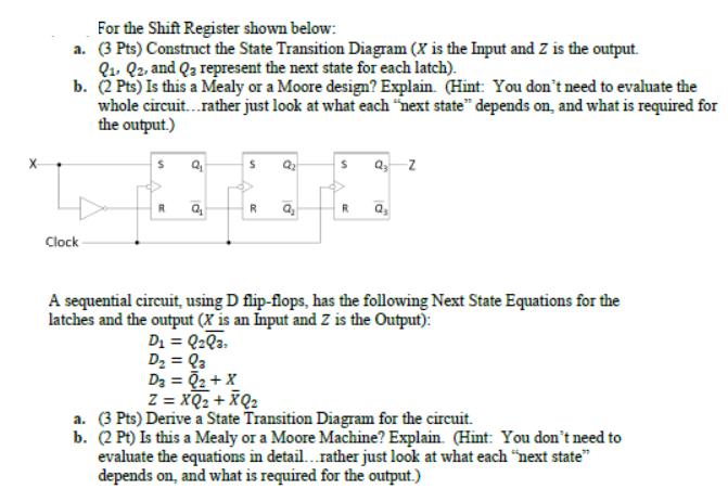
For the Shift Register shown below: a. (3 Pts) Construct the State Transition Diagram (X is the Input and Z is the output. Q Q2, and Q represent the next state for each latch). b. (2 Pts) Is this a Mealy or a Moore design? Explain. (Hint: You don't need to evaluate the whole circuit...rather just look at what each "next state" depends on, and what is required for the output.) Clock S R d Q R D = Q2Q3 D = Qa D = Q + X 8 a Q Z R Q A sequential circuit, using D flip-flops, has the following Next State Equations for the latches and the output (X is an Input and Z is the Output): Z = XQ + XQ a. (3 Pts) Derive a State Transition Diagram for the circuit. b. (2 Pt) Is this a Mealy or a Moore Machine? Explain. (Hint: You don't need to evaluate the equations in detail...rather just look at what each "next state" depends on, and what is required for the output.)
Step by Step Solution
3.37 Rating (144 Votes )
There are 3 Steps involved in it
For the given shift register and sequential circuit with D flipflops well first construct the state ... View full answer

Get step-by-step solutions from verified subject matter experts