

Question: Task 2: One-bit Full Adder: The Kamaugh maps for the full-adder are shown in Figure 1. Carr B Sumb oool1@OO ooo1@120 od 1 o 0
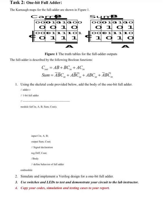
Task 2: One-bit Full Adder: The Kamaugh maps for the full-adder are shown in Figure 1. Carr B Sumb oool1@OO ooo1@120 od 1 o 0 1 0 1 OOD111101 DO011110 o 1 1 1 #1 1 o 1 0 C Figure 1 The truth tables for the full-adder outputs The full-adder is described by the following Boolean functions: Cour = AB+BC+ AC Sum= ABC, + ABC + ABC + ABC 1. Using the skeletal code provided below, add the body of the one-bit full adder. // adder 1/ 1-bit fulladder module fa(Cin, A. B, Sum, Cout). input Cin, AB output Sum, Cout // Signal declaration teg Diff, Cout Body // define behavior of fulladder endmodule 2. Simulate and implement a Verilog design for a one-bit full adder. 3. Use switches and LEDs to test and demonstrate your circuit to the lab instructor. 4. Copy your codes, simulation and testing cases to your report
Step by Step Solution
There are 3 Steps involved in it

Get step-by-step solutions from verified subject matter experts