

Question: Team Project Goal: Use Cisco Packet Tracer ( PT ) to design an Access LAN with at least two subnets for the 3 r d
Team Project
Goal:
Use Cisco Packet Tracer PT to design an Access LAN with at least two subnets for the floor of the UTEP student residence building.
Physical Layout of the Floor
Eloors
Some Requirements:
a Please refer to the above figure for the overall floor layout ie the locations of the lobby and rooms Your team can assume a size for the floorlobbyroom bedrooms based on your preference or the physical sizes of a real building floor and corresponding rooms.
b At least two VLANs are required on the switches. You can choose to assign any roomstudent to any VLANs. Routing between VLANs should be achieved via either routers eg ROAS or Layer switches.
c Please cover the lobby area with wireless only or wireless plus some wired connections. Wireless access to all the rooms is required.
d The completed LAN should have at least one gateway to the external Internet eg you can useconfig servers or clouds to represent external Internet
Deliverables:
The TeamName pkt file from PT including:
a the physical design of your network make sure you have all the devices wired in the MDFwiring closet You can either arrange and locateclear everything physically floorlobbyrooms in PT or import the physical design into PT from other drawing software eg SmartDraw you prefer.
Note: as the physical design in PT has not been covered in class, this deliverable is optional. But it would be good to include the physical design as well to make the whole project complete. Maybe you can leave this part to the last when you have completed everything else. For the physical design in PT you can get help either from me or from the free PT introduction course you received when you registered for the Cisco Network Academy account.
b the logical design of your network. You need to have two subnets and two VLANs at least; make sure you provide the details of your subnets and VLANs eg a table of subnet number, subnet mask and IP
addresses range for all the subnetshostsbroadcasts You can provide your subnet info either based on the real IP address info used in PT or on a theoretical subnet design matching the needs of all the students on the floor of the building.
c the capacity planning of your network make sure you run the simulation and the whole network is working Please provide the traffic assumptions you used for capacity planning. For example, you can assume there is mainly webmail application traffic in your network although this will never happen in the real world and estimate bandwidth for each userroom You can provide detailed capacity planning either in a note in PT or in your final presentation slides.
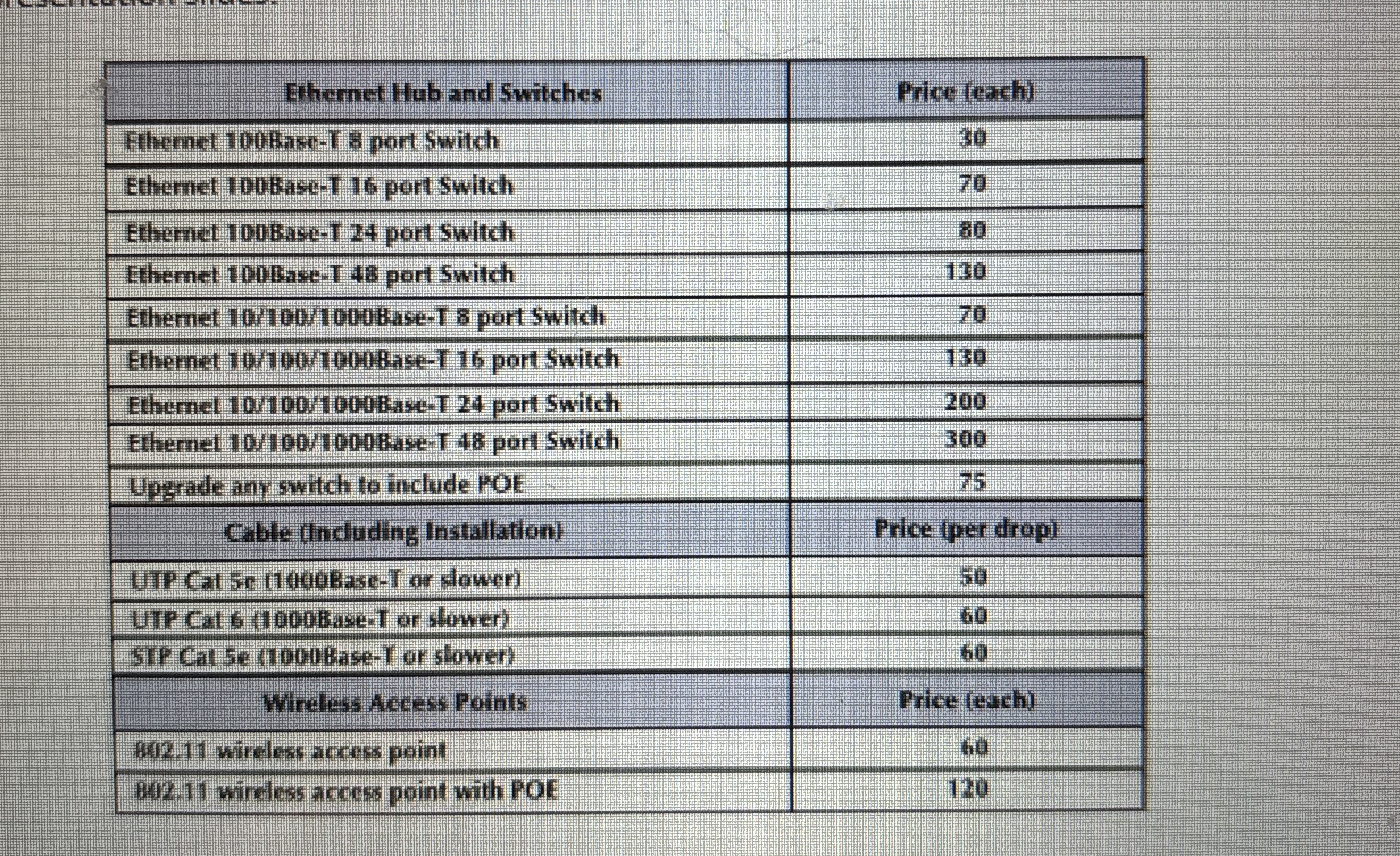
d the cost assessment for the hardwareequipment The hardware you have chosen should result from the above capacity planning. Please provide a list of the costs of your network excluding costs of software and network management and maintenance Please use the table below as a general guideline for cost assessment. Please use other cost sources eg
wwwcdwcom when the cost info is unavailable in the table eg cost of the routers You can provide your detailed cost assessment either in a note in PT or in your final presentation slides.
Step by Step Solution
There are 3 Steps involved in it
1 Expert Approved Answer
Step: 1 Unlock

Question Has Been Solved by an Expert!
Get step-by-step solutions from verified subject matter experts
Step: 2 Unlock
Step: 3 Unlock