

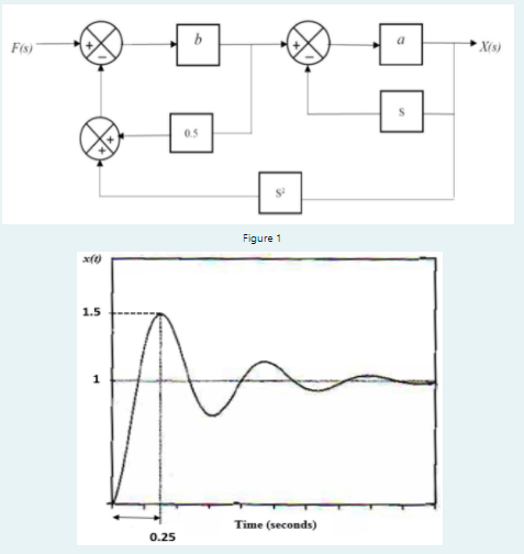
Question: The block diagram representing a mechanical system is shown in Figure 1 . The desired set point to controllers is F ( s ) =
The block diagram representing a mechanical system is shown in Figure The desired set point to controllers is Fss The system vibrates as shown in Figure
i Find the transfer function of XsFs by reducing the block diagram
ii Determine the value of a and b
iii Find the steady state error of the system
Step by Step Solution
There are 3 Steps involved in it
1 Expert Approved Answer
Step: 1 Unlock

Question Has Been Solved by an Expert!
Get step-by-step solutions from verified subject matter experts
Step: 2 Unlock
Step: 3 Unlock