

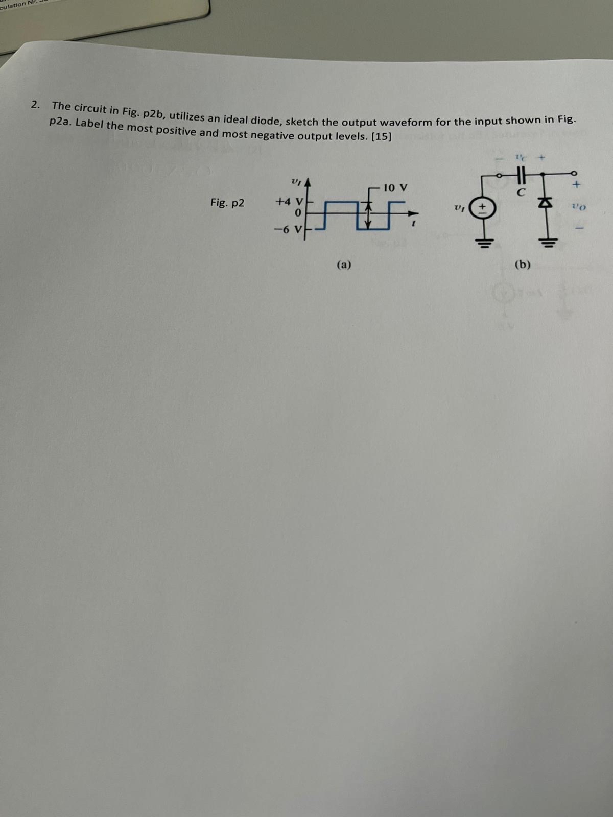
Question: The circuit in Fig. p 2 b , utilizes an ideal diode, sketch the output waveform for the input shown in Fig. p 2 a
The circuit in Fig. pb utilizes an ideal diode, sketch the output waveform for the input shown in Fig. pa Label the most positive and most negative output levels.
a
b
Step by Step Solution
There are 3 Steps involved in it
1 Expert Approved Answer
Step: 1 Unlock

Question Has Been Solved by an Expert!
Get step-by-step solutions from verified subject matter experts
Step: 2 Unlock
Step: 3 Unlock