

Question: The circuit shown below is called an SR Latch. Draw the output signals Q and Q' for the given inputs, and label each section of
The circuit shown below is called an SR Latch. Draw the output signals Q and Q' for the given inputs, and label each section of the trace as "set", "reset", "no change", etc.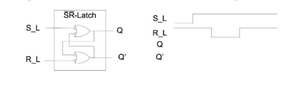
SR-Latch S L S L R L R L
Step by Step Solution
There are 3 Steps involved in it
1 Expert Approved Answer
Step: 1 Unlock

Question Has Been Solved by an Expert!
Get step-by-step solutions from verified subject matter experts
Step: 2 Unlock
Step: 3 Unlock