

Question: The Function ( description ) Design a logic system that has eight inputs ( a 1 , a 2 , a 3 , a 4
The Function description
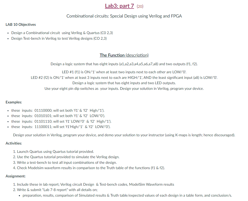
Design a logic system that has eight inputs aaaaaaaa and two outputs f f
LED #f is ON when at least two inputs next to each other are LOWO
LED #f is ON when at least inputs next to each are HIGH AND the least significant input a is LOW
Design a logic system that has eight inputs and two LED outputs.
Use your eight pin dip switches as your inputs. Design your solution in Verilog, program your device.
Examples:
these inputs: ; will set both f& f High
these inputs: ; will set both f& f LOW
these inputs: ; will set f LOW& f High
these inputs: ; will set f'High& f LOW
Design your solution in Verilog, program your device, and demo your solution to your instructor using Kmaps is length; hence discouraged
Activities:
Launch Quartus using Quartus tutorial provided.
Use the Quartus tutorial provided to simulate the Verilog design.
Write a testbench to test all input combinations of the design.
Check Modelsim waveform results in comparison to the Truth table of the functions f & f
Assignment:
Include these in lab report; Verilog circuit Design & Testbench codes, ModelSim Waveform results
Write & submit "Lab report" with all details on;
preparation, results, comparison of Simulated results & Truth tableexpected values of each design in a table form, and conclusions
Step by Step Solution
There are 3 Steps involved in it
1 Expert Approved Answer
Step: 1 Unlock

Question Has Been Solved by an Expert!
Get step-by-step solutions from verified subject matter experts
Step: 2 Unlock
Step: 3 Unlock