

Question: The graph shown in figure 1 describes a 3-input (x2, x1, x0), 2-output (Z1, Z0) sequential circuit. Assume that the initial state is A and
The graph shown in figure 1 describes a 3-input (x2, x1, x0), 2-output (Z1, Z0) sequential circuit. Assume that the initial state is "A" and write the sequence of states and outputs reached by the circuit when the input pattern shown in table 1 is received.
Note: Write the state/output pairs at t0, t1, t2 and t3, separated by a space. Example: If in t0 the circuit goes from A to C and output associated to state C is 11, then in t1 remains at C; in t2 changes to state D with an output associated to state D equal to 00, and finally in t3 changes to state E with output 10, you should write C/11 C/11 D/00 E/10
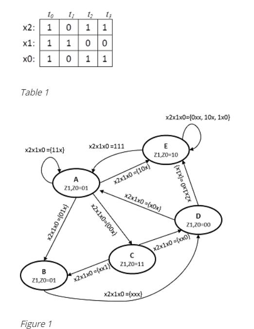
to 10 11 2: x1: 1 1 0: 1 1 1 Table 1 x2x1x0={0xx, 10x, 1x0} x2x1x0 =(11x} x2x1x0 =111 E Z1,20-10 A x2x1x0 ={10x} 21,20-01 x2x1x0=(x0x) 21,20-00 x2x1x0 ={xx0) 21,20-11 B Z1,70-01 x2x1x0 ={xx1) x2x1x0 =(xxx} Figure 1 x2x1x0={00x} x2x1x0 ={x1x}
Step by Step Solution
3.39 Rating (168 Votes )
There are 3 Steps involved in it
To solve the problem you will need to trace the sequential circuit using the given ... View full answer

Get step-by-step solutions from verified subject matter experts