

Question: The mode setting push button is used in a toggle fashion to select one-output-valve and two-output-valves operation. In the two-output-valves two valves are watering the
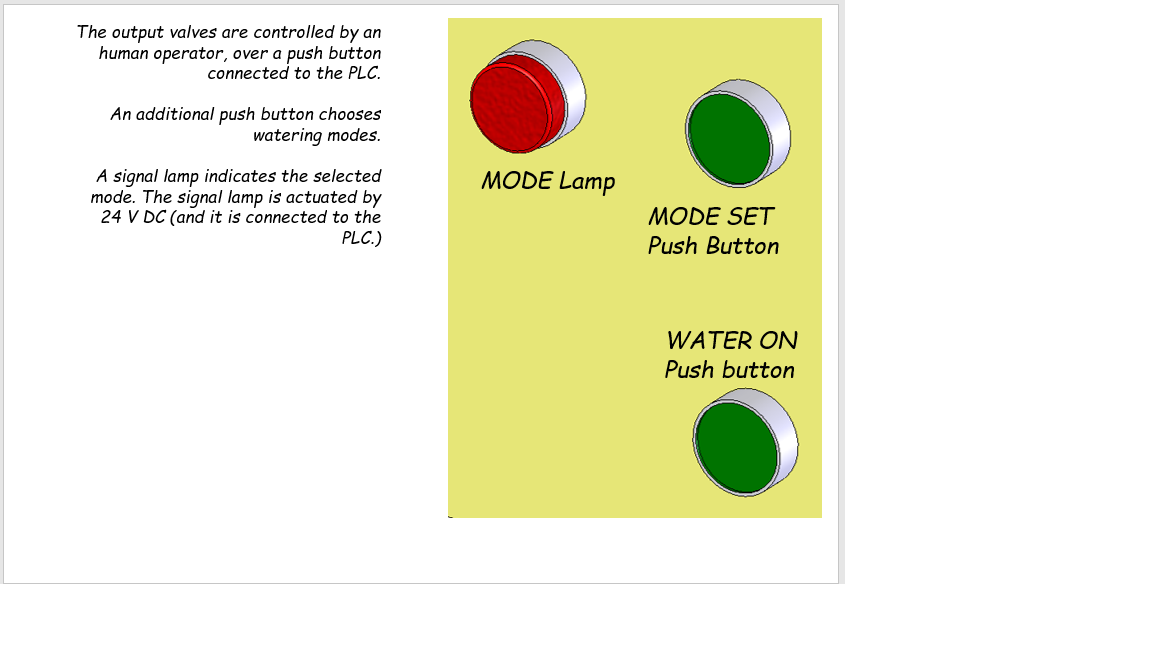
The mode setting push button is used in a toggle fashion to select one-output-valve and two-output-valves operation. In the two-output-valves two valves are watering the garden at the same time. The mode lamp should shine in the two-output-valves mode.
The valve which is to be activated in the one-output-valve mode is to be entered in a graphical user interface (HMI).
Water should flow to the garden with the command of the water-on push button. This button is enabled or disabled from the graphical user interface. The staus of the enable system should be shown on the graphical user interface.
Tank filling operation is to be programmed in two modes:
-Fill up to the high level mode
-Fill up to the medium level mode
When the level drops below the low level sensor, the input valve should be activated until the water level reaches the high or medium level, depending on the filling mode.
The filling mode is selected and displayed on the graphical user interface.
Step by Step Solution
There are 3 Steps involved in it

Get step-by-step solutions from verified subject matter experts