

Question: The system shown in the circuit below has two switches as input sensors. The output is connected to two sets of LEDs. Set1 has L1
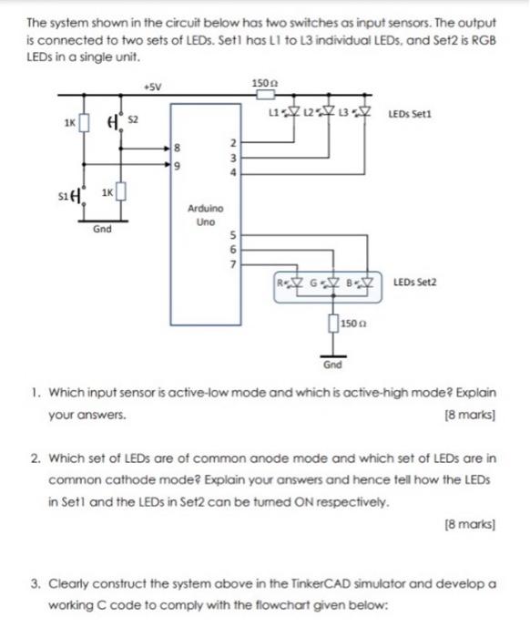

The system shown in the circuit below has two switches as input sensors. The output is connected to two sets of LEDs. Set1 has L1 to L3 individual LEDs, and Set2 is RGB LEDs in a single unit. 1. Which input sensor is active-low mode and which is active-high mode? Explain your answers. [ 8 marks] 2. Which set of LEDs are of common anode mode and which set of LEDs are in common cathode mode? Explain your answers and hence tell how the LEDs in Set1 and the LEDs in Set2 can be tumed ON respectively. [8 marks] 3. Clearly construct the system above in the TinkerCAD simulator and develop a working C code to comply with the flowchart given below: Submission: a. Submit all answers via the ulearn system. b. Your C code in plaintext format. c. Screen capture of your TinkerCAD circuit connection. d. Answers to questions 1 and 2 can be in Ms Word file format
Step by Step Solution
There are 3 Steps involved in it

Get step-by-step solutions from verified subject matter experts